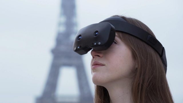
French startup Lynx hasn’t had an easy time of getting headsets out the door, much less funding its small hardware startup, which is dedicated to producing its R-1 mixed reality standalone. There seems to be some light at the end of the tunnel though, as Lynx CEO Stan Larroque announced that a batch of R-1 headsets should be shipping out soon.
Larroque details the plan to distribute an additional 400 units between July and August in a recent Kickstarter update, noting that the units were assembled earlier but were delayed due to financial issues with the assembler Compal.
While those issues have now been resolved and those headsets are set to ship, Larroque details what he calls an “excruciating” last 12 months, which he maintains isn’t related to the headset itself, but rather the tough fundraising environment for XR hardware in Europe.
“We were supposed to close a 30M€ deal at the end of April, term sheet signed and everything. And it didn’t happened [sic] because the European investor didn’t really have the money and lied to us. This was almost a death sentence, it’s the worst thing that can happen to a startup,” Larroque says.
Reeling from the admitted near death sentence, the company suffered another setback with a French public fund:
“Another one is a French public fund lying to us in their will to commit to our company. They took more than 6 months to do a due diligence, we spent hundreds of hours on the case with them (they were supposed to commit 15M€). They issued a [letter of intent] in July 2023. All that to realize they were badmouthing about us behind our backs to other potential co-investors. A VC shared those emails with me and it depressed me so much.”
Lynx announced some additional positive news. In the update, Larroque says the company is now collaborating with a “big financial US partner,” and remains optimistic about its product and roadmap, noting there is significant interest in defense, industrial, and medical sectors.
The company has attracted additional funding outside of R-1’s successful Kickstarter campaign from late 2021, which brought in $800,000 in crowd funds. In 2019, prior to the Kickstarter, Lynx secured a seed round of $2 million. According to data obtained by Crunchbase, its most recent Series A secured in 2022 from Somnium Space, bringing to the startup $4 million, making for a total of $6.8 million in funding to date.
Similar to Meta Quest 3 or Apple Vision Pro, Lynx R-1 provides mixed reality experiences thanks to its passthrough sensors and onboard Snapdragon XR2 chipset, although the company hopes to make it a more open and versatile device.
Update 2/21/22: I added a discussion of the DLP’s new frame rates and its potential to address field sequential color breakup.
Introduction
In part 3 of my combined CES and AR/VR/MR 2024 coverage of over 50 Mixed Reality companies, I will discuss display companies.
As discussed in Mixed Reality at CES and the AR/VR/MR 2024 Video (Part 1 – Headset Companies), Jason McDowall of The AR Show recorded more than four hours of video on the 50 companies. In editing the videos, I felt the need to add more information on the companies. So, I decided to release each video in sections with a companion blog article with added information.
Outline of the Video and Additional Information
The part of the video on display companies is only about 14 minutes long, but with my background working in displays, I had more to write about each company. The times in blue on the left of each subsection below link to the YouTube video section discussing a given company.
Lighting Silicon is a spinoff of Kopin’s micro-OLED development. Kopin started making micro-LCD microdisplays with its transmissive color filter “Lift-off LCOS” process in 1990. 2011 Kopin acquired Forth Dimension Displays (FDD), a high-resolution Ferroelectric (reflective) LCOS maker. In 2016, I first reported on Kopin Entering the OLED Microdisplay Market. Lighting Silicon (as Kopin) was the first company to promote the combination of all plastic pancake optics with micro-OLEDs (now used in the Apple Vision Pro). Panasonic picked up the Lighting/Kopin OLED with pancake optics design for their Shift All headset (see also: Pancake Optics Kopin/Panasonic).
At CES 2024, I was invited by Chris Chinnock of Insight Media to be on a panel at Lighting Silicon’s reception. The panel’s title was “Finding the Path to a Consumer-Friendly Vision Pro Headset” (video link – remember this was made before the Apple Vision Pro was available). The panel started with Lighting Silicon’s Chairman, John Fan, explaining Lighting Silicon and its relationship with Lakeside Lighting Semiconductor. Essentially, Lightning Semiconductor designs the semiconductor backplane, and Lakeside Lighting does the OLED assembly (including applying the OLED material a wafer at a time, sealing the display, singulating the displays, and bonding). Currently, Lakeside Lighting is only processing 8-inch/200mm wafers, limiting Lighting Silicon to making ~2.5K resolution devices. To make ~4K devices, Lighting Semiconductor needs a more advanced semiconductor process that is only available in more modern 12-inch/300mm FABs. Lakeside is now building a manufacturing facility that can handle 12-inch OLED wafer assembly, enabling Lighting Silicon to offer ~4K devices.
Related info on Kopin’s history in microdisplays and micro-OLEDs:
RaonTech seems to be one of the most popular LCOS makers, as I see their devices being used in many new designs/prototypes. Himax (Google Glass, Hololens 1, and many others) and Omnivision (Magic Leap 1&2 and other designs) are also LCOS makers I know are in multiple designs, but I didn’t see them at CES or the AR/VR/MR. I first reported on RaonTech at CES 2018 (Part 1 – AR Overview). RaonTech makes various LCOS devices with different pixel sizes and resolutions. More recently, they have developed a 2.15-micron pixel pitch field sequential color pixel with an “embedded spatial interpolation is done by pixel circuit itself,” so (as I understand it) the 4K image is based on 2K data being sent and interpolated by the display.
In addition to LCOS, RaonTech has been designing backplanes for other companies making micro-OLED and MicroLED microdisplays.
May Display is a Korean LCOS company that I first saw at CES 2022. It surprised me, as I thought I knew most of the LCOS makers. May is still a bit of an enigma. They make a range of LCOS panels, their most advanced being an 8K (7980 x 4,320) 3.2-micron pixel pitch. May also makes a 4K VR headset with a 75-degree FOV using their LCOS devices.
May has its own in-house LCOS manufacturing capability. May demonstrated using its LCOS devices in projectors and VR headsets and showed them being used in a (true) holographic projector (I think using phase LCOS).
May Display sounds like an impressive LCOS company, but I have not seen or heard of their LCOS devices being used in other companies’ products or prototypes.
As discussed earlier with Lighting Silicon, Kopin acquired Ferroelectric LCOS maker Forth Dimension Displays (FDD) in 2011. FDD was originally founded as Micropix in 1988 as part of CRL-Opto, then renamed CRLO in 2004, and finally Forth Dimension Displays in 2005, before Kopin’s 2011 acquisition.
I started working in LCOS in 1998 as the CTO of Silicon Display, a startup developing a VR/AR monocular headset. I designed an XGA (1024 x768) LCOS backplane and the FGA to drive it. We were looking to work with MicroPix/CRL-Opto to do the LCOS assembly (applying the cover glass, glue seal, and liquid crystal). When MicroPix/CRL-Opto couldn’t get their backplane to work, they ended up licensing the XGA LCOS backplane design I did at Silicon Display to be their first device, which they had made for many years.
FDD has focused on higher-end display applications, with its most high-profile design win being the early 4K RED cameras. But (almost) all viewfinders today, including RED, use OLEDs. FDD’s LCOS devices have been used in military and industrial VR applications, but I haven’t seen them used in the broader AR/VR market. According to FDD, one of the biggest markets for their devices today is in “structured light” for 3-D depth sensing. FDD’s devices are also used in industrial and scientific applications such as 3D Super Resolution Microscopy and 3D Optical Metrology.
Around 2015, DLP and LCOS displays seemed to have been used in roughly equal numbers of waveguide-based AR/MR designs. However, since 2016, almost all new waveguide-based designs have used LCOS, most notably the Hololens 1 (2016) and Magic Leap One (2018). Even companies previously using DLP switched to LCOS and, more recently, MicroLEDs with new designs. Among the reasons the companies gave for switching from DLP to LCOS were pixel size and, thus, a smaller device for a given resolution, lower power consumption of the display+asic, more choice in device resolutions and form factors, and cost.
While DLP does not require polarized light, which is a significant efficiency advantage in room/theater projector applications that project hundreds or thousands of lumens, the power of the display device and control logic/ASICs are much more of a factor in near-eye displays that require less than 1 to at most a few lumens since the light is directly aimed into the eye rather than illuminating the whole room. Additionally, many near-eye optical designs employ one or more reflective optics requiring polarized light.
Another issue with DLP is drive algorithm control. Texas Instruments does not give its customers direct access to the DLP’s drive algorithm, which was a major issue for CREAL (to be discussed in the next article), which switched from DLP to LCOS partly because of the need to control its unique light field driving method directly. VividQ (also to be discussed in the next article), which generates a holographic display, started with DLP and now uses LCOS. Lightspace 3D has similarly switched.
Far from giving up, TI is making a concerted effort to improve its position in the AR/VR/MR market with new, smaller, and more efficient DLP/DMD devices and chipsets and reference design optics.
Color Breakup On Hololens 1 using a low color sequential field rate
Added 2/21/22: I forgot to discuss the DLP’s new frame rates and field sequential color breakup.
I find the new, much higher frame rates the most interesting. Both DLP and LCOS use field sequential color (FSC), which can be prone to color breakup with eye and/or image movement. One way to reduce the chance of breakup is to increase the frame rate and, thus, the color field sequence rate (there are nominally three color fields, R, G, & B, per frame). With DLP’s new much higher 240Hz & 480Hz frame rates, the DLP would have 720 or 1440 color fields per second. Some older LCOS had as low as 60-frames/180-fields (I think this was used on Hololens 1 – right), and many, if not most, LCOS today use 120-frames/360-fields per second. A few LCOS devices I have seen can go as high as 180-frames/540-fields per second. So, the newer DLP devices would have an advantage in that area.
I worked at Texas Instruments from 1977 to 1998, becoming the youngest TI Fellow in the company’s history in 1988. However, contrary to what people may think, I never directly worked on the DLP. The closest I came was a short-lived joint development program to develop a DLP-based color copier using the TMS320C80 image processor, for which I was the lead architect.
I worked in the Microprocessor division developing the TMS9918/28/29 (the first “Sprite” video chip), the TMS9995 CPU, the TMS99000 CPU, the TMS34010 (the first programmable graphics processor), the TMS34020 (2nd generation), the TMS302C80 (first image processor with 4 DSP CPUs and a RISC CPU) several generations of Video DRAM (starting with the TMS4161), and the first Synchronous DRAM. I designed silicon to generate or process pixels for about 17 of my 20 years at TI.
After leaving TI, ended up working on LCOS, a rival technology to DLP, from 1998 through 2011. But then when I was designing a aftermarket autmotive HUD at Navdy, I chose use a DLP engine for the projector for its advantages in that application. I like to think of myself as a product focused and want to use whichever technology works best for the given application. I see pros and cons in all the display technologies.
VueReal is a Canadian-based startup developing MicroLEDs. Their initial focus was on making single color per device microdisplays (below left).
However, perhaps VueReal’s most interesting development is their cartridge-based method of microprinting MicroLEDs. In this process, they singulate the individual LEDs, test and select them, and then transfer them to a substrate with either passive (wire) or active (ex., thin-film transistors on glass or plastic). They claim to have extremely high yields with this process. With this process, they can make full-color rectangular displays (above right), transparent displays (by spacing the LEDs out on a transparent substrate, and displays of various shapes, such as an automotive instrument panel or a tail light.
MojoVision is pivoting from a “Contact Lens Display Company” to a “MicroLED component company.” Its new CEO is Dr. Nikhil Balram, formerly the head of Google’s Display Group. MojoVision started saying (in private) that it was putting more emphasis on being a MicroLEDs component company around 2021. Still, it didn’t publicly stop developing the contact lens display until January 2023 after spending more than $200M.
To be clear, I always thought the contact lens display concept was fatally flawed due to physics, to the point where I thought it was a scam. Some third-party NDA reasons kept me from talking about MojoVision until 2022. I outlined some fundamental problems and why I thought the contact lens display was a sham in my 2022 Video with Brad Lynch on Mojovision Contact Display in my 2022 CES Discussion video with Brad Lynch (if you take pleasure in my beating up on a dumb concept for about 14 minutes, it might be a fun thing to watch).
So, in my book, Mojovision, the company starts with a major credibility problem. Still, they are now under new leadership and focusing on what they got to work, namely very small MicroLEDs. Their 1.75-micron LEDs are the smallest I have heard about. The “old” Mojovision had developed direct/native green MicroLEDs, but the new MojoVision is developing native blue LEDs and then using quantum dot conversion to get green and red.
I have been hearing about using quantum dots to make full-color MicroLEDs for ~10 years, and many companies have said they are working on it. Playnitride demonstrated quantum dot-converted microdisplays (via Lumus waveguides) and larger direct-view displays at AR/VR/MR 2023 (see MicroLEDs with Waveguides (CES & AR/VR/MR 2023 Pt. 7)).
Mike Wiemer (CTO) gave a presentation on “Comparing Reds: QD vs InGaN vs AlInGaP” (behind the SPIE Paywall). Below are a few slides from that presentation.
Wiemer gave many of the (well-known in the industry) advantages of the blue LED with the quantum dot approach for MicroLEDs over competing approaches to full-color MicroLEDs, including:
Blue LEDs are the most efficient color
You only have to make a single type of LED crystal structure in a single layer.
It is relatively easy to print small quantum dots; it is infeasible to pick and place microdisplay size MicroLEDs
Quantum dots converted blue to green and red are much more efficient than native green and red LEDs
Native red LEDs are inefficient in GaN crystalline structures that are moderately compatible with native green and blue LEDs.
Stacking native LEDs of different colors on different layers is a complex crystalline growth process, and blocking light from lower layers causes efficiency issues.
Single emitters with multiple-color LEDs (e.g., See my article on Porotech) have efficiency issues, particularly in RED, which are further exacerbated by the need to time sequence the colors. Controlling a large array of single emitters with multiple colors requires a yet-to-be-developed, complex backplane.
Some of the known big issues with quantum dot conversion with MicroLED microdisplays (not a problem for larger direct view displays):
MicroLEDs can only have a very thin layer of quantum dots. If the layer is too thin, the light/energy is wasted, and the residual blue light must be filtered out to get good greens and reds.
MojoVision claims to have developed quantum dots that can convert all the blue light to red or green with thin layers
There must be some structure/isolation to prevent the blue light from adjacent cells from activating the quantum dots of a given cell, which would cause the desaturation of colors. Eliminating color crosstalk/desaturating is another advantage of having thinner quantum dot layers.
The lifetime and potential for color shifting with quantum dots, particularly if they are driven hard. Native crystalline LEDs are more durable and can be driven harder/brighter. Thus, quantum dot-converted blue LEDs, while more than 10x brighter than OLEDs, are expected to be less bright than native LEDs
While MojoVision has a relatively small 1.37-micron LED on a 1.87-micron pitch, that still gives a 3.74-micron pixel pitch (assuming MojoVision keeps using two reds to get enough red brightness). While this is still about half the pixel pitch of the Apple Vision’s Pro ~7.5-micron pitch OLED, a smaller pixel size such as with a single-emitter-with multiple-colors (e.g., Porotech) would be better (more efficient due to étendue see: MicroLEDs with Waveguides (CES & AR/VR/MR 2023 Pt. 7)) for semi-collimating the light using microlenses as needed by waveguides.
While technically interesting, Porotech’s single-emitter device will likely take considerable time to perfect. The single-emitter approach has the major advantage of supporting a smaller pixel since only one LED per pixel is required. This also results in only two electrical connections (power and ground) to LED per pixel.
However, as the current level controls the color wavelength, this level must be precise. The brightness is then controlled by the duty cycle. An extremely advanced semiconductor backplane will be needed to precisely control the current and duty cycle per pixel, a backplane vastly more complex than LCOS or spatial color MicroLEDs (such as MojoVision and Playnitride) require.
Using current to control the color of LEDs is well-known to experts in LEDs. Multiple LED experts have told me that based on their knowledge, they believe Porotech’s red light output will be small relative to the blue and green. To produce a full-color image, the single emitter will have to sequentially display red, green, and blue, further exacerbating the red’s brightness issues.
Brilliance has developed a 3-color laser combiner on silicon. Light guides formed in/on the silicon act similarly to fiber optics to combine red, green, and blue laser diodes into a single beam. The obvious application of this technology would be a laser beam scanning (LBS) display.
While I appreciate Brilliance’s technical achievement, I don’t believe that laser beam scanning (LBS) is a competitive display technology for any known application. This blog has written dozens of articles (too many to list here) about the failure of LBS displays.
14:24 TriLite/Trixel (Laser Combiner and LBS Display Glasses)
Last and certainly least, we get to TriLite Laser Beam Scanning (LBS) glasses. LBS displays for near-eye and projector use have a perfect 25+ year record of failure. I have written about many of these failures since this blog started. I see nothing in TriLite that will change this trend. It does not matter if they shoot from the temple onto a hologram directly into the eye like North Focals or use a waveguide like TriLite; the fatal weak link is using an LBS display device.
It has reached the point when I see a device with an LBS display. I’m pretty sure it is either part of a scam and/or the people involved are too incompetent to create a good product (and yes, I include Hololens 2 in this category). Every company with an LBS display (once again, including Hololens 2) lies about the resolution by confabulating “scan lines” with the rows of a pixel-based display. Scan lines are not the same as pixel rows because the LBS scan lines vary in spacing and follow a curved path. Thus, every pixel in the image must be resampled into a distorted and non-uniform scanning process.
Like Brilliance above, TriLites’ core technology combines three lasers for LBS. Unlike Brilliance, TriLites does not end up with the beams being coaxial; rather, they are at slightly different angles. This will cause the various colors to diverge by different amounts in the scanning process. TriLite uses its “Trajectory Control Module” (TCM) to compute how to re-sample the image to align the red, green, and blue.
The information and images below have been collected from TriLite’s website.
As far as I have seen, it is a myth that LBS has any advantage in size, cost, and power over LCOS for the same image resolution and FOV. As discussed in part 1, Avegant generated the comparison below, comparing North Focals LBS glasses with a ~12-degree FOV and roughly 320×240 resolution to Avegant’s 720 x 720 30-degree LCOS-based glasses.
Below is a selection (from dozens) of related articles I have written on various LBS display devices:
I plan to cover non-display devices next in this series on CES and AR/VR/MR 2024. That will leave sections on Holograms and Lightfields, Display Measurement Companies, and finally, Jason and my discussion of the Apple Vision Pro.
I planned to wrap up my first pass coverage of the Apple Vision Pro (AVP) with my summary and conclusions based on prior articles. But the more I thought about it, Apple’s approach to Passthrough Mixed Reality (PtMR) seems like it will be so egregiously bad that it should be broken out and discussed separately.
Apple Prioritized EyeSight “Gimmick” Over Ergonomics and Functionality
There are some features, particularly surrounding camera passthrough, where there should have been an internal battle between those who wanted the EyeSight™ gimmick and what I would consider more important functionality. The backers of EyeSight must have won and forced the horrible location of the passthrough cameras, optical distortion from the curved glass in front of all the forward-facing cameras and sensors, put a fragile piece of hard-to-replace glass on the front where it can be easily scratched and broken, and added weight to the front were it is least desired. Also, as discussed later, there are negative effects on the human visual system caused by misaligning the passthrough cameras with the eyes.
The negative effects of EyeSight are so bad for so many fundamental features that someone in power with little appreciation for the technical difficulties must have forced the decision (at least, that is the only way I can conceive of it happening). People inside the design team must have known it would cause serious problems. Supporting passthrough mixed reality (PtMR) is hard enough without deliberately creating problems.
Meta Quest 3 Camera Location
As noted in Meta Quest Pro (Part 1) – Unbelievably Bad AR Passthrough, Meta is locating the soon-to-be-released Quest 3 main passthrough camera closer to the center of view of the eyes. Fixed cameras in front of the eyes won’t be perfect and will still require digital correction for better functional use. It does appear that Meta is taking the PtMR more seriously than it did with the Meta Quest Pro and Quest 2.
I’m going to be looking forward to getting a Meta Quest 3 to test out when it is released soon.
Definitions of AR/VR/MR and PtMR
The terms used to describe mixed reality have been very fluid over the last few years. Before the introduction of Hololens, Augmented reality meant any headset that displayed virtual content on a see-through display. For example, just before Hololens went on sale, Wired in 2015 titled their article (with my bold emphasis): Microsoft Shows HoloLens’ Augmented Reality Is No Gimmick. With the introduction of Hololens, the term “Mixed Reality” was used to distinguish AR headsets with SLAM to lock the virtual to the real world. “AR” headsets without SLAM are sometimes called AR Heads-Up Displays (HUDs), but these get confused with automotive HUDs. Many today refer to a see-through headset without SLAM as “AR” and one with SLAM as “MR,” whereas previously, the terms “AR” covered both with and without SLAM.
Now we have the added confusion of optical see-through (e.x. Hololens) and camera passthrough “Mixed Reality.” While they may be trying to accomplish similar capabilities, they are radically different in their capabilities. Rather than constantly typing “passthrough” before MR, I abbreviated it as PtMR.
In Optical AR, the Virtual Content Augments the Real World – With PtMR, the Real World Augments the Virtual Content
Optical MR prioritizes seeing the real world at the expense of the virtual content. The real world is in perfect perspective, at the correct focus distance, with no limitation by a camera or display on brightness, with zero lag, etc. If done well, there is minimal light blocking and distortion of the real world and little blocking of the real-world FOV.
PtMR, on the other hand, prioritizes virtual image quality at the expense of the real world, both in how things behave in 3-D space (focus perspective) and in image quality.
We are likely many decades away, if ever, from passing what Douglas Lanman of Meta calls their Visual Turing Test (see also the video linked here).
Meta’s demonstrations at Siggraph 2023 of their Flamera with perspective-correct passthrough and Butterscotch with vergence accommodation conflict served to show how far PtMR is from optical passthrough. They can only address each problem individually, each with a large prototype, and even then, there are severe restrictions. The Flamera has a very low-resolution passthrough, and Butterscotch only supports a 50-degree FOV.
It is also interesting that Butterscotch moves back from Half Dome 3’s electronic LCD variable focus to electro-mechanical focusing to address VAC. As reported in Mixed Reality News, “However, the technology presented problems with light transmission and image quality [of the electronic LCD approach], so Meta discarded it for Butterscotch Varifocal at the expense of weight and size.”
All of this work is to try and solve some of the many problems created by PtMR that don’t exist with optical MR. PtMR does not “solve” the issues with optical MR. It just creates a long list of massively hard new problems. Optical AR has issues with the image quality of the virtual world, very large FOV, and hard-edge occlusion (see my article Magic Leap 2 (Pt. 3): Soft Edge Occlusion, a Solution for Investors and Not Users). I often say, “What is hard in optical MR is easy in PtMR and vice versa.”
Demo or Die
Meta and others seem to use Siggraph to show off research work that is far from practical. As stated by Lanman of Meta, of their Flamera and Butterscotch VAC demos at Siggraph 2023, Meta’s Reality Labs has a “Demo or Die” philosophy. They will not be tipping off their competition on concepts they will use within a few years. To be clear, I’m happy to see companies showing off their technical prowess, but at the same time, I want to put it in perspective.
Cosmetic vs. Functional Passthrough PtMR
JayzTwoCents video on the HTC Vive XR Elite has a presentation by Phil on what he calls “3D Depth Projection” (others refer to it as “perspective correct“). In the video (sequence of clips below), Phil demonstrates that because the passthrough video was not corrected in scale, position, and perspective in 3-D space, it deprives him of hand-eye coordination to catch a bottle tossed to him.
Phil demonstrated in the video (and in a sequence of clips below) that with the Meta Quest Pro, even though the image quality is much worse and distorted due to the 3D projection, he can at least catch the bottle.
I would classify the HTC Vive XR Elite as having a “Cosmetic Passthrough.” While the image quality is better (but still not very good), it is non-functional. While Meta Quest Pro’s image quality is lousy, it is at least somewhat functional.
Something else to notice in the MQP frame sequence above is that there are both lag and accuracy errors in hand tracking.
Effects on Vision with Long-Term Use
It is less obvious that the human visual system will start adapting to any camera placement and then have to re-adapt after the headset is removed. This was briefly discussed in AVP Part 2 in the section titled Centering correctly for the human visual system, which references Steve Mann in his March 2013 IEEE Spectrum article, “What I’ve learned from 35 years of wearing computerized eyewear.” In the early days with Steve Mann, they had no processing power to attempt to move the effect of the camera images digitally. At the same time, I’m not sure how well the correction will work or how a distorted view will affect people’s visual perception during and after long exposure. As with most visual effects, it will vary from one individual to another.
To reduce any undesired negative effects on human vision caused by cameras not aligning with the eyes, some devices, such as the Quest 2 and Quest Pro from Meta, use processing to create what I will call “virtual cameras” with a synthesized view for each eye. The farther the physical cameras are from the eye’s location, the larger the correction will be required and the larger the distortion in the final result.
Meta at Siggraph 2023 presented the paper “Perspective-Correct VR Passthrough Without Reprojection” (and IEEE article) and showed their Flamera prototype with a light field camera (right). The figure below shows how the camera receives light rays from the same angle as the eye with the Light Field Passthrough Camera.
Below are a couple of still frames (with my annotations) from the related video that show how, with the Meta Quest 2, the eye and camera views differ (below left), resulting in a distorted image (below right). The distortion/error as the distance from the eye decreases.
It should be noted that while Flamera’s light field camera approach addresses the angular problems of the camera location, it does so with a massive loss in resolution (by at least “n,” where n is the number of light field subviews). So, while interesting in terms of research and highlighting the problem, it is still a highly impractical approach.
Poster Zee2 took exception to my article and seemed to feel I was understating the problem of 3-D perspective. I think Zee2 missed what I meant by “pyrrhic victory.” I was trying to say they were correct to address the 3D depth issue but that doing so with a massive loss in image quality was not the solution. I was not dismissing the importance of perspective-correct passthrough.
Below, I am copying his comment from that thread (with my bold highlighting)), including a quote from my article. Interestingly, Zee2 comments on Varjo having good image quality with its passthrough, but it is not perspective-correct.
I also really don’t know why he [refering to my article] decided to deemphasize the perspective and depth correctness so much. He mentions it here:
>[QuotingMeta Quest Pro (Part 1) – Unbelievably Bad AR Passthrough]In this case, they were willing to sacrifice image quality to try to make the position of things in the real world agree with where virtual objects appear. To some degree, they have accomplished this goal. But the image quality and level of distortion, particularly of “close things,” which includes the user’s hands, is so bad that it seems like a pyrrhic victory.
I don’t think this is even close to capturing how important depth and perspective correct passthrough is.
Reprojecting the passthrough image onto a 3D representation of the world mesh to reconstruct a perspective-correct view is the difference between a novelty that quickly gives people headaches and something that people can actually wear and look through for an extended period of time.
Varjo, as a counterexample, uses incredibly high-resolution cameras for their passthrough. The image quality is excellent, text is readable, contrast is good, etc. However, they make no effort to reproject their passthrough in terms of depth reconstruction. The result is a passthrough image that is very sharp, but is instantly, painfully, nauseatingly uncomfortable when walking around or looking at closeup objects alongside a distant background.
The importance of depth-correct passthrough reprojection (essentially, spacewarp using the depth info of the scene reconstruction mesh) absolutely cannot be understated and is a make or break for general adoption of any MR device. Karl is doing the industry a disservice with this article.
Does the AVP have Cosmetic or Functional PtMR or Something Else?
With the AVP’s passthrough cameras being so poorly located (thanks to EyeSight™), severe distortion would seem inevitable to support functional PtMR. I don’t believe there is some magic (perhaps a pun on Magic Leap) that Apple could employ that Meta couldn’t that would simultaneously support good image quality without serious distortion with the terrible camera placement due to the Eyesight(tm) feature.
So, based on the placement of the cameras, I have low expectations for the functionality of the AVP’s PtMR. The “instant experts” who got to try out the AVP would be more impressed by a cosmetically better-looking passthrough. Since there are no reports of distortion like the MQP, I’m left to conclude that, at least for the demo, they were only doing a cosmetic passthrough.
As I often say, “Nobody will volunteer information, but everyone will correct you.” Thus, it is better to take a position based on the current evidence and then wait for a correction or confirmation from the many developers with AVPs who read this blog.
Conclusion
I’m not discounting the technical and financial power of Apple. But then I have been writing about the exaggerated claims for Mixed Reality products by giant companies such as Google, Meta, and Microsoft, not to mention the many smaller companies, including the over $3B spent by Magic Leap, for the last ten years. The combined sunk cost of about $50B of these companies, not including Apple. As I’m fond of saying, “If all it took were money and smart people, it would already be solved.”
Apple doesn’t fully appreciate the difficulties with Passthrough Mixed Reality, or they wouldn’t prioritize the EyeSight gimmick over core capabilities. I’m not saying the AVP would work well for passthrough AR without EyeSight, but it is hard enough without digging big technical holes to support a novelty feature.


