Did that rock move, or is it a squirrel crossing the road? Tracking objects that look a lot like their surroundings is a big problem for many autonomous vision systems. AI algorithms can solve this camouflage problem, but they take time and computing power. A new camera designed by researchers in South Korea provides a faster solution. The camera takes inspiration from the eyes of a cat, using two modifications that let it distinguish objects from their background, even at night.
“In the future … a variety of intelligent robots will require the development of vision systems that are best suited for their specific visual tasks,” says Young Min Song, a professor of electrical engineering and computer science at Gwangju Institute of Science and Technology and one of the camera’s designers. Song’s recent research has been focused on using the “perfectly adapted” eyes of animals to enhance camera hardware, allowing for specialized cameras for different jobs. For example, fish eyes have wider fields of view as a consequence of their curved retinas. Cats may be common and easy to overlook, he says, but their eyes actually offer a lot of inspiration.
This particular camera copied two adaptations from cats’ eyes: their vertical pupils and a reflective structure behind their retinas. Combined, these allowed the camera to be 10 percent more accurate at distinguishing camouflaged objects from their backgrounds and 52 percent more efficient at absorbing incoming light.
Using a vertical pupil to narrow focus
While conventional cameras can clearly see the foreground and background of an image, the slitted pupils of a cat focus directly on a target, preventing it from blending in with its surroundings. Kim et al./Science Advances
In conventional camera systems, when there is adequate light, the aperture—the camera’s version of a pupil—is small and circular. This structure allows for a large depth of field (the distance between the closest and farthest objects in focus), clearly seeing both the foreground and the background. By contrast, cat eyes narrow to a vertical pupil during the day. This shifts the focus to a target, distinguishing it more clearly from the background.
The researchers 3D printed a vertical slit to use as an aperture for their camera. They tested the vertical slit using seven computer vision algorithms designed to track moving objects. The vertical slit increased contrast between a target object and its background, even if they were visually similar. It beat the conventional camera on five of the seven tests. For the two tests it performed worse than the conventional camera, the accuracies of the two cameras were within 10 percent of each other.
Using a reflector to gather additional light
Cats can see more clearly at night than conventional cameras due to reflectors in their eyes that bring extra light to their retinas.Kim et al./Science Advances
Cat eyes have an in-built reflector, called a tapetum lucidum, which sits behind the retina. It reflects light that passes through the retina back at it, so it can process both the incoming light and reflected light, giving felines superior night vision. You can see this biological adaptation yourself by looking at a cat’s eyes at night: they will glow.
The researchers created an artificial version of this biological structure by placing a silver reflector under each photodiode in the camera. Photodiodes without a reflector generated current when more than 1.39 watts per square meter of light fell on them, while photodiodes with a reflector activated with 0.007 W/m2 of light. That means the photodiode could generate an image with about 1/200th the light.
Each photodiode was placed above a reflector and joined by metal electrodes to create a curved image sensor.Kim et al./Science Advances
To decrease visual aberrations (imperfections in the way the lens of the camera focuses light), Song and his team opted to create a curved image sensor, like the back of the human eye. In such a setup, a standard image sensor chip won’t work, because it’s rigid and flat. Instead it often relies on many individual photodiodes arranged on a curved substrate. A common problem with such curved sensors is that they require ultrathin silicon photodiodes, which inherently absorb less light than a standard imager’s pixels. But reflectors behind each photodiode in the artificial cat’s eye compensated for this, enabling the researchers to create a curved imager without sacrificing light absorption.
Together, vertical slits and reflectors led to a camera that could see more clearly in the dark and isn’t fooled by camouflage. “Applying these two characteristics to autonomous vehicles or intelligent robots could naturally improve their ability to see objects more clearly at night and to identify specific targets more accurately,” says Song. He foresees this camera being used for self-driving cars or drones in complex urban environments.
Song’s lab is continuing to work on using biological solutions to solve artificial vision problems. Currently, they are developing devices that mimic how brains process images, hoping to one day combine them with their biologically-inspired cameras. The goal, says Song, is to “mimic the neural systems of nature.”
Song and his colleague’s work was published this week in the journal Science Advances.
Scottish inventor
John Logie Baird had a lot of ingenious ideas, not all of which caught on. His phonovision was an early attempt at video recording, with the signals preserved on phonograph records. His noctovision used infrared light to see objects in the dark, which some experts claim was a precursor to radar.
But Baird earned his spot in history with the televisor. On 26 January 1926, select members of the Royal Institution gathered at Baird’s lab in London’s Soho neighborhood to witness the broadcast of a small but clearly defined image of a ventriloquist dummy’s face, sent from the televisor’s electromechanical transmitter to its receiver. He also demonstrated the televisor with a human subject, who observers could see speaking and moving on the screen. For this, Baird is often credited with the first public demonstration of television.
John Logie Baird [shown here] used the heads of ventriloquist dummies in early experiments because they didn’t mind the heat and bright lights of his televisor. Science History Images/Alamy
How the Nipkow Disk Led to Baird’s Televisor
To be clear, Baird didn’t invent television. Television is one of those inventions that benefited from many contributors, collaborators, and competitors. Baird’s starting point was an idea for an “electric telescope,” patented in 1885 by German engineer
Paul Nipkow.
Nipkow’s apparatus captured a picture by dividing it into a vertical sequence of lines, using a spinning disk with perforated holes around the edge. The perforations were offset in a spiral so that each hole captured one slice of the image in turn—known today as scan lines. Each line would be encoded as an electrical signal. A receiving apparatus converted the signals into light, to reconstruct the image. Nipkow never commercialized his electric telescope, though, and after 15 years the patent expired.
The inset on the left shows how the televisor split an image (in this case, a person’s face) into vertical lines. Bettmann/Getty Images
The system that Baird demonstrated in 1926 used two Nipkow disks, one in the transmitting apparatus and the other in the receiving apparatus. Each disk had 30 holes. He fitted the disk with glass lenses that focused the reflected light onto a photoelectric cell. As the transmitting disk rotated, the photoelectric cell detected the change in brightness coming through the individual lenses and converted the light into an electrical signal.
This signal was then sent to the receiving system. (Part of the receiving apparatus,
housed at the Science Museum in London, is shown at top.) There the process was reversed, with the electrical signal first being amplified and then modulating a neon gas–discharge lamp. The light passed through a rectangular slot to focus it onto the receiving Nipkow disk, which was turning at the same speed as the transmitter. The image could be seen on a ground glass plate.
Early experiments used a dummy because the many incandescent lights needed to provide sufficient illumination made it too hot and bright for a person. Each hole in the disk captured only a small bit of the overall image, but as long as the disk spun fast enough, the brain could piece together the complete image, a phenomenon known as persistence of vision. (In a 2022 Hands On column, Markus Mierse explains how to build a
modern Nipkow-disk electromechanical TV using a 3D printer, an LED module, and an Arduino Mega microcontroller.)
John Logie Baird and “True Television”
Regular readers of
this column know the challenge of documenting historical “firsts”—the first radio, the first telegraph, the first high-tech prosthetic arm. Baird’s claim to the first public broadcast of television is no different. To complicate matters, the actual first demonstration of his televisor wasn’t on 26 January 1926 in front of those esteemed members of the Royal Institution; rather, it occurred in March 1925 in front of curious shoppers at a Selfridges department store.
As Donald F. McLean recounts in his excellent June 2022 article “Before ‘True Television’: Investigating John Logie Baird’s 1925 Original Television Apparatus,” Baird used a similar device for the Selfridges demo, but it had only 16 holes, organized as two groups of eight, hence its nickname the Double-8. The resolution was about as far from high definition as you could get, showing shadowy silhouettes in motion. Baird didn’t consider this “true television,” as McLean notes in his Proceedings of the IEEE piece.
In 1926, Baird loaned part of the televisor he used in his Selfridges demo to the Science Museum in London.PA Images/Getty Images
Writing in December 1926 in
Experimental Wireless & The Wireless Engineer, Baird defined true television as “the transmission of the image of an object with all gradations of light, shade, and detail, so that it is seen on the receiving screen as it appears to the eye of an actual observer.” Consider the Selfridges demo a beta test and the one for the Royal Institution the official unveiling. (In 2017, the IEEE chose to mark the latter and not the former with a Milestone.)
The 1926 demonstration was a turning point in Baird’s career. In 1927 he established the
Baird Television Development Co., and a year later he made the first transatlantic television transmission, from London to Hartsdale, N.Y. In 1929, the BBC decided to give Baird’s system a try, performing some experimental broadcasts outside of normal hours. After that, mechanical television took off in Great Britain and a few other European countries.
But Wait There’s More!
If you enjoyed this dip into the history of television, check out
Spectrum’s new video collaboration with the YouTube channel Asianometry, which will offer a variety of perspectives on fascinating chapters in the history of technology. The first set of videos looks at the commercialization of color television.
Head over to Asianometry to see how Sony finally conquered the challenges of mass production of color TV sets with its Trinitron line. On
Spectrum’s YouTube channel, you’ll find a video—written and narrated by yours truly—on how the eminent physicist Ernest O. Lawrence dabbled for a time in commercial TVs. Spoiler alert: Lawrence had much greater success with the cyclotron and government contracts than he ever did commercializing his Chromatron TV. Spectrum also has a video on the yearslong fight between CBS and RCA over the U.S. standard for color TV broadcasting. —A.M.
The BBC used various versions of Baird’s mechanical system from 1929 to 1937, starting with the 30-line system and upgrading to a 240-line system. But eventually the BBC switched to the all-electronic system developed by Marconi-EMI. Baird then switched to working on one of the earliest electronic
color television systems, called the Telechrome. (Baird had already demonstrated a successful mechanical color television system in 1928, but it never caught on.) Meanwhile, in the United States, Columbia Broadcasting System (CBS) attempted to develop a mechanical color television system based on Baird’s original idea of a color wheel but finally ceded to an electronic standard in 1953.
Baird also experimented with stereoscopic or three-dimensional television and a 1,000-line display, similar to today’s high-definition television. Unfortunately, he died in 1946 before he could persuade anyone to take up that technology.
In a
1969 interview in TV Times, John’s widow, Margaret Baird, reflected on some of the developments in television that would have made her husband happy. He would enjoy the massive amounts of sports coverage available, she said. (Baird had done the first live broadcast of the Epsom Derby in 1931.) He would be thrilled with current affairs programs. And, my personal favorite, she thought he would love the annual broadcasting of the Eurovision song contest.
Other TV Inventors: Philo Farnsworth, Vladimir Zworykin
But as I said, television is an invention that’s had many contributors. Across the Atlantic,
Philo Farnsworth was experimenting with an all-electrical system that he had first envisioned as a high school student in 1922. By 1926, Farnsworth had secured enough financial backing to work full time on his idea.
One of his main inventions was the image dissector, also known as a dissector tube. This video camera tube creates a temporary electron image that can be converted into an electrical signal. On 7 September 1927, Farnsworth and his team successfully transmitted a single black line, followed by other images of simple shapes. But the system could only handle silhouettes, not three-dimensional objects.
Meanwhile,
Vladimir Zworykin was also experimenting with electronic television. In 1923, he applied for a patent for a video tube called the iconoscope. But it wasn’t until 1931, after he joined RCA, that his team developed a working version, which suspiciously came after Zworykin visited Farnsworth’s lab in California. The iconoscope overcame some of the dissector tube’s deficiencies, especially the storage capacity. It was also more sensitive and easier to manufacture. But one major drawback of both the image dissector and the iconoscope was that, like Baird’s original televisor, they required very bright lights.
Everyone was working to develop a better tube, but Farnsworth claimed that he’d invented both the concept of an electronic image moving through a vacuum tube as well as the idea of a storage-type camera tube. The iconoscope and any future improvements all depended on these progenitor patents. RCA knew this and offered to buy Farnsworth’s patents, but Farnsworth refused to sell. A multiyear patent-interference case ensued, finally finding for Farnsworth in 1935.
While the case was being litigated, Farnsworth made the first public demonstration of an all-electric television system on 25 August 1934 at the Franklin Institute in Philadelphia. And in 1939, RCA finally agreed to pay royalties to Farnsworth to use his patented technologies. But Farnsworth was never able to compete commercially with RCA and its all-electric television system, which went on to dominate the U.S. television market.
Eventually, Harold Law, Paul Weimer, and Russell Law developed a better tube at their Princeton labs, the image orthicon. Designed for TV-guided missiles for the U.S. military, it was 100 to 1,000 times as sensitive as the iconoscope. After World War II, RCA quickly adopted the tube for its TV cameras. The image orthicon became the industry standard by 1947, remaining so until 1968 and the move to color TV.
The Path to Television Was Not Obvious
My Greek teacher hated the word “television.” He considered it an abomination that combined the Greek prefix
telos (far off) with a Latin base, videre (to see). But early television was a bit of an abomination—no one really knew what it was going to be. As Chris Horrocks lays out in his delightfully titled book, The Joy of Sets(2017), television was developed in relation to the media that came before—telegraph, telephone, radio, and film.
Was television going to be like a telegraph, with communication between two points and an image slowly reassembled? Was it going to be like a telephone, with direct and immediate dialog between both ends? Was it going to be like film, with prerecorded images played back to a wide audience? Or would it be more like radio, which at the time was largely live broadcasts? At the beginning, people didn’t even know they wanted a television; manufacturers had to
convince them.
And technically, there were many competing visions—Baird’s, Farnsworth’s, Zworykin’s, and others. It’s no wonder that television took many years, with lots of false starts and dead ends, before it finally took hold.
Part of a continuing series looking at historical artifacts that embrace the boundless potential of technology.
An abridged version of this article appears in the September 2024 print issue as “The Mechanical TV.”
References
In 1936, a fire destroyed the Crystal Palace, where Baird had workshops, a television studio, and a tube manufacturing plant. With it went lab notebooks, correspondence, and original artifacts, making it more difficult to know the full history of Baird and his contributions to television.
For an overview on the history of television, check out Chris Horrocks’s
The Joy of Sets: A Short History of the Television(Reaktion Books, 2017). Chapter 2 focuses on Baird and other early inventors. And if you want to learn more about Farnsworth’s and RCA’s battle, which doesn’t acknowledge Baird at all, see Evan Schwartz’s 2000 MIT Technology Review piece, “Who Really Invented Television?”
Researchers used Game of Thrones to study how the brain recognizes faces, providing insights into prosopagnosia, a condition affecting facial recognition in 1 in 50 people. MRI scans showed increased brain activity in regions associated with character knowledge in fans of the series, but reduced activity in those unfamiliar with the show and in prosopagnosia patients.
Based on information gathered at SID Display Week and AWE, I have many articles to write based on the thousands of pictures I took and things I learned. I have been organizing and editing the pictures.
As its name implies, Display Week is primarily about display devices. My major takeaway from that conference is that many companies work on full-color MicroLEDs with different approaches, including quantum dot color conversion, stack layers, and single emitter with color shifting based on current or voltage.
AWE moved venues from the Santa Clara Convention Center in Silicon Valley to the larger Long Beach Convention Center south of LA. More than just a venue shift, I sensed a shift in direction. Historically, at AWE, I have seen many optical see-through AR/MR headsets, but there seem to be fewer optical headsets this year. Instead, I saw many companies with software running on VR/Passthrough AR headsets, primarily on the Meta Quest 3 (MQ3)and Apple Vision Pro (AVP).
This article was partly inspired by Hypervision’s white paper discussing whether micro-OLEDs or small LCDs were the best path to 60 pixels per degree (PPD) with a wide FOV combined with the pictures I captured through Hypervision’s HO140 (140° diagonal FOV per eye) optics at AWE 2024. I have taken thousands of pictures through various headsets, and the Hypervision picture stood out in terms of FOV and sharpness. I have followed Hypervision since 2021 (see Appendix: More on Hypervision).
I took my first pictures at AWE through the Sony XR (SXR) Headset optics. At least subjectively, in a short demo, the SXR’s image quality (sharpness and contrast) seemed higher than that of the AVP, but the FOV was smaller. I had on hand (thousands) of pictures I had taken through the Big Screen Beyond (BSB), AVP, Meta Quest Pro (MQP), and Meta Quest 3 (MQ3) optics with the same camera and lens, plus a few of the Hypervision HO140 prototype. So, I decided to make some comparisons between various headsets.
I also want to mention LightPolymers’ new Quarter Waveplate (QWP) and Polarization technologies, which I first learned about from a poster in the Hypervision AWE booth. In April 2024, the two companies announced a joint development grant. They offer an alternative to the plastic film QWP and Polarizers, where 3M dominates today.
Hypervision’s HO140 Display
Based on my history of seeing Hypervision’s 240° prototypes for the last three years, I had, until AWE 2024, largely overlooked their single display 140° models. I had my Canon R5 (45Mp with 405mp ” 3×3 sensor pixel shift mode”) and tripod with me at AWE this year, so I took a few high-resolution pictures through the optics of the HO140. Below are pictures of the 240° (left) and 140° (right) prototypes in the Hypervsion Booth. Hypervision is an optics company and not a headset maker and the demos are meant to show off their optics.
When I got home and looked at the pictures through the HO140, I was impressed by the overall image quality of the HO140, after having taken thousands of pictures through the Apple Vision Pro (with Micro-OLED displays) and Meta’s Quest Pro, Quest 3 (both with mini-LCD displays), the Big Screen Beyond. It usually takes me considerable time and effort, as well as multiple reshoots, to find the “sweet spot” for the other devices, but I got good pictures through the HO140 with minimal effort and only a few pictures, which suggests a very large sweet spot in Hypervision’s optical design. The HO140 is a prototype of unknown cost that I am comparing to production products.I only have this one image to go by and not a test pattern.
The picture below is from my Canon R5, with a 16mm lens netting a FOV of 97.6° horizontal by 73.7° vertical. It was shot at 405mp and then reduced to 45mp to avoid moiré effects due to the “beat frequencies” between the camera sensor and the display devices with their color subpixels. All VR optics pincushion, which causes the pixel sizes to vary across the display and increases the chance of getting moiré in some regions.
The level of sharpness throughout the HO140’s image relative to other VR headsets suggests that it could support a higher-resolution LCD panel with a smaller pixel size if it existed. Some significant chroma aberrations are visible in the outer parts of the image, but these could be largely corrected in software.
Compared to other VR-type headsets I have photographed, I was impressed by how far out into the periphery of the FOV the image maintains sharpness while supporting a significantly larger FOV than any other device I have photographed. What I can’t tell without being able to run other content, such as test patterns, is the contrast of the display and optics combination.
AWE was my first time trying the new Sony XR (SXR) headset. In my CES 2024 coverage, I wrote about the ergonomic features I liked in Sony XR (and others compared to Apple Vision Pro). In particular, I liked the headband approach with the flip-up display, and my brief try with the Sony headset at AWE seemed to confirm the benefits of this design choice (which is very similar to the Lynx R1 headset), at least from the ergonomics perspective relative to the Apple Vision Pro.
Still, the SXR is still pretty big and bulky, much more so than the AVP or Lynx. Having only had a short demo, I can’t say how comfortable it will be in extended use. As was the case for the HO140, I couldn’t control the content.
“Enterprise” Product
Sony has been saying that this headset primarily aims at “enterprise” (= expensive high-end) applications, and they partner with Siemens. It is much more practical than the Apple Vision Pro (AVP). The support on the head is better; it supports users wearing their glasses, and the display/visor flips up so you can see the real world directly. There is air circulation to the face and eyes. The headset also supports adjustment of the distance from the headset to the eyes. The headset allows peripheral vision but does have a light shield for full VR operation. The headset is also supposed to support video passthrough, but that capability was not demonstrated. As noted in my CES article, the SXR headset put the pass-through cameras in a much better position than the AVP.
Display Devices and Image Quality
Both the AVP and SXR use ~4K micro-OLED display devices. While Sony does the OLED Assembly (applying the OLED and packaging) for its headset and the AVP’s display devices, the AVP reportedly uses a custom silicon backplane designed by Apple. The SXR’s display has ~20% smaller 6.3-micron pixels than the AVP’s 7.5-micron. The device size is also smaller. The size factors of the SXR favor higher angular resolution and a smaller FOV, as is seen with the SXR.
The picture below was taken (handheld) with my 45MP Canon R5 camera with a 16mm lens like the HO140, but because I couldn’t use a tripod, I couldn’t get a 405MP picture with the camera’s sensor shifting. I was impressed that I got relatively good images handheld, which suggests the optics have a much larger sweet spot than the AVP, for example. To get good images with the AVP requires my camera lens to be precisely aligned into the relatively small sweep spot of the AVP’s optics (using a 6-degree-of-freedom camera rig on a tripod). I believe the Apple Vision Pro’s small sweet spot and the need for eye-tracking-based lens correction, and not just for foveated rendering, are part of why the AVP has to be uncomfortably clamped against the user’s face.
Given that I was hand-holding both the headset and camera, I was rather surprised that the pictures came out so well (click on the image to see it in higher, 45mp resolution).
At least in my brief demo, the SXR’s optics image quality seems better than the AVP’s. The images seem sharper with lesser chroma (color) aberrations. The AVP seems heavily dependent on eye tracking to correct optics problems with the optics, but it does not always succeed.
Much more Eye Refief (enabling eye glasses) but lower FOV
I was surprised by how much eye relief the SXR optics afforded compared to the AVP and BSB, which also use Micro-OLED microdisplays. Typically, the requirement for high magnification of the micro-OLED pixels compared to LCD pixels inherently makes eye relief more difficult. The SXR magnifies less, resulting in a smaller FOV, but also makes it easier optically for them to support more eye relief. But note, taking advantage of the greater eye relief will further reduce the FOV. The SXR headset has a smaller FOV than any other VR-type headset I have tried recently.
Novel Sony controllers were not a hit
While I will credit Sony for trying something new with the controllers, I didn’t like finger trackpad and ring color are great solutions. I talked with several people who tried them, and no one seemed to like either controller. It is hard to judge control devices in a short demo; you must work with them for a while. Still, they didn’t make a good first impression.
VR Headset “Shootout” between AVP, MQP, Big Screen Beyond, Hypervision, and Sony XR
I have been shooting VR headsets with the Canon R5 with a 16mm lens for some time and built up a large library of pictures. For the AVP, Big Screen Beyond (BSB), and Meta Quest Pro (MQP), I had both the the headset and the camera locked down on tripods so I could center the lens in the sweet spot of the optics. For the Hypervision, while the camera and headset were on tripods, my camera was only on a travel tripod without my 6-degree-of-freedom rig and the time to precisely locate the headset’s optical sweet spot. The SXR picture was taken with my hand holding the headset and the camera.
Below are through-the-optics pictures of the AVP, BSB, MQP, Hypervision HO140, and SXR headsets, all taken with the same camera and lens combination and scaled identically. This is not a perfect comparison as the camera lens does not work identically to the eye (which also rotates), but it is reasonably close. The physically shorter and simpler 16mm prime (non-zoom) lens lets it get inside the eye box of the various headsets for the FOV it can capture.
FOV Comparison (AVP, SXR, BSB, HO140, MQ3/MQP)
While companies will talk about the number of horizontal and vertical pixels of the display device, the periphery of the display’s pixels are cut off by the optics, which tend to be circular. All the VR headset optics have a pincushion distortion, which results in higher resolution in the sweet spot (optical center), which is always toward the nose side and usually above the center for VR headsets.
In the figure below, I have overlaid the FOV of the left eye for the headsets on top of the picture HO140 image. I had to extrapolate somewhat on the image circles on the top and bottom as the headset FOVs exceeded the extent of the camera’s FOV. The HO140 supports up to a 2.9″ diagonal LCD (that does not exist yet), but they currently use a 2.56″ 2160×2160 Octagonal BOE LCD and are so far beyond the FOV of my camera lens that I used their information.
As can be seen, the LCD-based headsets of Hypervision and Meta typically have larger FOV than the micro-OLED-based headsets of AVP, Meta, and Sony. However, as will be discussed, the micro-OLED-based headsets have smaller pixels (angularly and on the physical display device).
Center Pixels (Angular Size in PPD)
Due to handholding the SXR and having pixels smaller than the AVP, I couldn’t get a super-high-resolution (405 mp) image from the center of the FOV and didn’t have the time to use a longer focal length lens to show the pixel boundaries. The SXR has roughly the same number of pixels as the AVP but a smaller FOV, so its pixels are angularly smaller than the AVP’s. I would expect the SXR to be near 60 pixels per degree (PPD) in the center of the FOV. The BSB has about the same FOV as the AVP but has a ~2.5K micro-OLED compared to the AVP’s ~4K; thus, the BSB pixels in the center are about 1.5x bigger (linearly). The Hypervision’s display has a slightly smaller center pixel pitch than the MQP (and MQ3) but with a massively bigger FOV.
The MQP (and the very similar MQ3) rotate the display device. To make it easier to compare the pixel pitches, I included a rotated inset of the MQP pixels to match the alignment of the other devices. Note that the pictures below are all “through the optics” and thus include the headset’s optical magnification. I have given the angular resolution in PPD for each headset. I have indicated the angular resolution (in pixels-per-degree, PPD) for each of the headset’s center pixels. For the center pixels pictures below, I used a 28mm lens to get more magnification to see sub-pixel detail for the AVP, BSB, and MQP. I only took 16mm lens pictures of the HO140 and, therefore, rescaled the image based on the different focal lengths of the lens.
The Micro-OLED base headsets require significantly more optical magnification than the LCD models. For example, the AVP has 3.2x (linearly) smaller display device pixels than the MQP, but after optics, the pixels are ~1.82x smaller. As a specific example, the AVP magnifies the display by ~1.76 more than the MQP.
Outer Pixels
I capture pixels from a similar (very approximately) distance from the optical center of the lens. The AVP’s “foveated rendering” makes it look worse than it is, but you can still see the pixel grid with the others. Of the micro-OLED headsets, the BSB and SXR seem to do the best regarding sharpness in the periphery. The Hypervision HO140 pixels seem much less distorted and blurry than any of the headsets, including the MQP and MP3, which have much smaller FOVs.
Micro-OLED vs. Mini-LCD Challenges
Micro-OLEDs are made by applying OLEDs on top of a CMOS substrate. CMOS transistors provide a high current per unit area, and all the transistors and circuitry are underneath the OLED pixels, so it doesn’t block light. These factors enable relatively small pixels of 6.3 to 10 microns. However, CMOS substrates are much more expensive per unit area, and modern semiconductor FABs limit of CMOS devices is about 1.4-inch diagonal (ignoring expensive and low-yielding “reticle stitched” devices).
A basic issue with OLEDs is that the display device must provide the power/current to drive each OLED. In the case of LCDs, only a small amount of capacitance has to be driven to change the pixel, after which there is virtually no current. The table on the right (which I discussed in 2017) shows the transistor mobility and the process requirements for the transistors for various display backplanes. The current need for an emitting display device like OLEDs and LEDs requires crystalline silicon (e.g., CMOS) or much larger thin-film transistors on glass. There are also issues of the size and resistivity of the wires used to provide the current and heat issues.
The OLED’s requirement for significant current/power limits how small the pixels can get on a given substrate/technology. Thin-film transistors have to be physically big to supply the current. For example, the Apple Watch Ultra Thin Film transistor OLED display has 326 PPI (~78 microns), which is more than 10x larger linearly (100x the area) than the Apple Vision Pro’s pixel, even though both are “OLEDs.”
Another issue caused by trying to support large FOVs with small devices is that the higher magnification reduces eye relief. Most of the “magnification” comes from moving the device closer to the eye. Thus, LCD headsets tend to have more eye relief. Sony’s XR headset is an exception because it has enough eye relief for glasses but does so with a smaller FOV than the other headsets.
Small LCDs used in VR displays have different challenges. They are made on glass substrates, and the transistors and circuitry must be larger. Because they are transmissive, this circuitry in the periphery of each pixel blocks light and causes more of a screen door effect. The cost per unit area is much lower than that of CMOS, and LCD devices can be much larger. Thus, less aggressive optical magnification is required for the same FOV with LCDs.
LCDs face a major challenge in making the pixels smaller to support higher resolution. As the pixels get smaller, the size of the circuitry relative to the pixel size becomes bigger, blocking more light and causing a worse screen door effect. To make the pixels smaller, they must develop higher-performance thin-film transistors and lower resistance interconnection to keep blocking too much light. This subject is discussed in an Innolux Research Paper published by SPIE in October 2023 (free to download). Innolux discusses how to go from today’s typical “small” LCD pixel of 1200 ppi (=~21 microns) to their research device with 2117 ppi (=~12 microns) to achieve a 3840 x 3840 (4K by 4k) display in a 2.56″ diagonal device. Hypervision’s HO140 white paper discusses Innolux’s 2022 research prototype with the same pixel size but with 3240×3240 pixels and a 2.27-inch panel, as well as the current prototype. The current HO140 uses a BOE 2.56″ 2160×2160 panel with 21-micron pixels, as the Innolux panel is not commercially available.
Some micro-OLED and small LCD displays for VR
YouTuber Brad Lynch of SadlyItsBradley, in an X post, listed the PPI of some common VR headset display devices. I have added more entries and the pixel pitch in microns. Many VR panels are not rectangular and may have cut corners on the bottom (and top). The size of the panels given in inches is for the longest diagonal. As you can see, Innolux’s prototypes have significantly smaller pixels, but almost 2x linearly, than the VR LCDs in volume production today:
Apple Vision Pro 1.4″ Micro-OLED,3,660×3,200, 3386 PPI (7.5 microns)
SeeYa 1.03″ Micro-OLED, 2560×2560, 3528 PPI (7.2 microns) – Used in Big Screen Beyond
Sony ~1.3″ Micro-OLED, 3552 x 3840, 4032 PPI (6.3 microns) – Sony XR
BOE 1.35″ Micro-OLED 3552×3840, 4032 PPI (6.3 microns) – Demoed at Display Week 2024
In 2017, I wrote Near Eye Displays (NEDs): Gaps In Pixel Sizes (table from that article on the right) talks about what I call the pixel size gap between microdisplays (on Silicon) and small LCDs (on glass). While the pixel sizes have gotten smaller for both micro-OLED and LCDs for VR in the last ~7 years, there remains a sizable gap.
Contrast – Factoring the Display and Pancake Optics
Micro-OLEDs at the display level certainly have a better inherent black level and can turn pixels completely off. LCDs work by blocking light using cross-polarization, which results in imperfect blacks. Thus, with micro-OLEDs, a large area of black will look black, whereas with LCDs, it will be dark gray.
However, we are not looking at the displays directly but through optics, specifically pancake optics, which dominate new VR designs today. Pancake optics, which use polarized light and QWP to recirculate the image twice through parts of the optics, are prone to internal reflections that cause “ghosts” (somewhat out-of-focus reflections) and contrast loss.
Using smaller micro-OLEDs requires more “aggressive” optical designs that support higher magnification to support a wide FOV. These more aggressive optical designs can be more prone to being more expensive, less sharp, and loss of polarization. Any loss of polarization in pancake optics will cause a loss of contrast and ghosting. There seems to be a tendency with pancake optics for the stray light to bounce around and end up in the periphery of the image, causing a glow if the periphery of the image is supposed to be black.
For example, the AVP is known to have an outer “glow” when watching movie content on a black background. Most VR headsets default to a “movie or home theater” rather than a background. While it may be for aesthetics, the engineer in me thinks it might help hide the glow. People online suggest turning on some background with the AVP for people bothered by the glow on a black background.
The complaints of outer glow when watching movies seem more prevalent when using headsets micro-OLEDs, but this is hardly scientific. It could be just that the micro-OLEDs have a better black level and make the glow more noticeable, but it might also be caused by their more aggressive optical magnification (something that might be or has been (?) studied). My key point is that it is not as simple as considering the display’s inherent contrast, you have to consider the whole optical system.
LightPolymers’ Alternative to Plastic Films for QWP & Polarizers
LightPolymers has a Lyotropic (water-based) Liquid Crystal (LC) material that can make optical surfaces like QWP and polarizers. Silicon Optix, which the blog broke the news of Meta buying them in December 2021 (Exclusive: Imagine Optix Bought By Meta), was also developing LC-based polarized light control films.
Like Silicon Optix, Light Polymers has been coating plastic films with LCs, but LightPolymers is developing the ability to directly apply their films to flat and curved lenses, which is a potential game changer. In April 2024, LightPolymers and Hypervision announced the joint development of this lens-coating technology and had a poster in their Hypervision’s booth showing it (right)
3M Dominates Polarized Light Plastic Films for Pancake Optics
3M is today the dominant player in polarized light-control plastic films and is even more dominant in these films for pancake optics. At 3M’s SID Display Week booth in June 2024, they showed the ByteDance PICO4, MQP, and MQ3 pancake optics using 3M polarization films. Their films are also used in the Fresnel lens-based Quest 2. It is an open secret (but 3M would not confirm or deny) that the Apple Vision Pro also uses 3M polarization films.
“3M did not invent the optical architecture of pancake lenses. However, 3M was the first company to successfully demonstrate the viability of pancake lenses in VR headsets by combining it with its patented reflective polarizer technology.“
That same article supports Kopin’s (now spun out to Lightning Silicon) claims to have been the first to develop pancake optics. Kopin has been demonstrating pancake optics combined with their Micro-OLEDs for years, which are used in Panasonic-ShiftAll headsets.
3M’s 2017 SPIE Paper Folded Optics with Birefringent Reflective Polarizers discusses the use of their films (and also mentions Kopin developments) in cemented (e.g., AVP) and air gap (e.g., MQP and MP3) pancake optics. The paper also discusses how their polarization films can be made (with heat softening) to conform to curved optics such as the AVP.
LightPolymers’ Potential Advantage over Plastic Films
The most obvious drawbacks of plastic films are that they are relatively thick (on the order of 70+ microns per film, and there are typically multiple films per lens) and are usually attached using adhesive coatings. The thickness, particularly when trying to conform to a curved surface, can cause issues with polarized light. The adhesives introduce some scatter, resulting in some loss of polarization.
By applying their LCs directly to the lens, LightPolymer claims they could reduce the thickness of the polarization control (QWP and Polarizers) by as much as 10x and would eliminate the use of adhesives.
In the photos below (taken with a 5x macro lens), I used a knife to slightly separate the edges of the films from the Meta Quest 3’s eye-side and display-side lenses to show them. On the eye-side lens, there are three films, which are thought to be a QWP, absorptive polarizer, and reflective polarizer. On the display-side lens, there are two films, one of which is a QWP, and the other may be just a protective film. In the eye-side lens photo, you can see where the adhesive has bubbled up after separation. The diagram on the right shows the films and paths for light with the MQ3/MQP pancake optics.
Because LighPolymers’ LC coating is applied to each lens, it could also be applied/patterned to improve or compensate for other issues in the optics.
Current State of LightPolymer’s Technology
LightPolymers is already applying its LC to plastic films and flat glass. Their joint agreement with Hypervision involves developing manufacturable methods for directly applying the LC coatings to curved lens surfaces. This technology will take time to develop. LightPolymer business of making the LC materials and then works with partners such as Hypervision to apply the LC to their lenses. They say the equipment necessary to apply the LCs is readily available and low-cost (for manufacturing equipment).
Conclusion
Hypervision has demonstrated the ability to design very wide FOV pancake optics with a large optical sweet spot and maintains a larger area of sharpness than any other design I have seen.
Based on my experience in both Semiconductors and Optics, I think Hypervision makes a good case in their white paper 60PPD: by fast LCD but not by micro OLED, getting to a wide FOV while approaching “retinal” 60PPD is more likely to happen using LCD technology than micro-OLEDs.
Fundamentally, micro-OLEDs are unlikely to get much bigger than 1.4″ diagonally, at least commercially, for many years, if not more than a decade. While they could make the pixels smaller, today’s pancake optics struggle to resolve ~7.5-micron pixels, no less small ones.
On the other hand, several companies, including Innoulux and BOE, have shown research prototypes of 12-micron LCD pixels, or half the (linear) size of today’s LCDs used in VR headsets in high volume. If BOE or Innolux went into production with these displays, it would enable Hypervision’s HO140 to reach about 48 PPD in the center with a roughly 140-degree FOV, and only small incremental changes would get them to 60 PPD with the same FOV.
I first encountered Hypervision at AWE 2021 with their blended Fresnel lens 240-degree design, but as this blog primarily covered optical AR, it slipped under my radar. Since then, I have been covering Optical and Pass-Through mixed reality, particularly pass-through MR using Pancake Optics. By AR/VR/MR 2023, Hypervsion demonstrated a single lens (per eye) 140-degree and a blended dual lens and display 240-degree FOV (diagonal) Pancake Optics designs.
These were vastly better than their older Fresnel designs and demonstrated Hypervision’s optical design capability. In May 2023, passthrough MR startup Lynx and Hypervision announced they were collaborating. For some more background on my encounters with Hypervision, see Hypervision Background.
New research reveals that individuals who experience vision loss before age 10 struggle more with judging sound distance compared to those who lose sight later in life. This difficulty in perceiving the location of sounds has significant implications for safety and navigation. The study highlights the need for tailored healthcare solutions for those with early vision loss to enhance their quality of life.
Researchers found that daily antioxidant supplements slow the progression of late-stage dry age-related macular degeneration (AMD). The supplements help preserve central vision by slowing the expansion of geographic atrophy regions in the retina. This finding supports the use of AREDS2 supplements for people with late dry AMD.
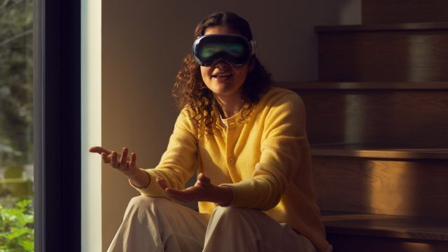
At $3,500, Vision Pro is undoubtedly expensive, which many are rightfully hoping will be remedied in a prospective follow-up. Now, according to a report from The Information, Apple may be ditching the ‘Pro’ aspect of its next-gen Vision headsets altogether, instead aiming to release a single “more affordable” device in late 2025.
It’s rumored that Apple was slated to release two headsets: an expensive Pro-style device and a cheaper version targeted more squarely at consumers, much like how the company positions iPhone in its lineup today.
Now, citing an employee at a manufacturer that makes key components for the Vision Pro, The Information reports Apple has suspended work on that high-end follow-up due to slowing sales of the $3,500 Vision Pro.
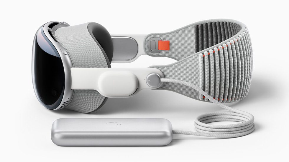
Image courtesy Apple
There may be hope though, at least for anyone without the budget to shell out what amounts to a good used Honda Civic. According sources both involved in the supply chain and in the manufacturing of the headset, the company is “still working on releasing a more affordable Vision product with fewer features before the end of 2025.”
Granted, it’s important to note that Apple often leaks incorrect information in a bid to nail prospective leakers, so this (and any Apple report for that matter) should be taken with a heaping handful of salt.
This follows Apple’s announcement it was getting set to release Vision Pro outside of the US for the first time, which includes mainland China, Hong Kong, Japan, Singapore, Australia, Canada, France, Germany, and the UK.
– – — – –
Whether it’s “more affordable” or not, there’s a lot Apple can do to appeal to the masses without drastically sacrificing quality. Check out our article on the 6 Things Vision Pro Needs Before It Can Go Mainstream to see how.
The AVP video amounts to a recap of the many articles I have written on the AVP. Where appropriate, I will give links to my more detailed coverage in prior articles and updates rather than rehash that information in this article.
It should be noted that Jason and I recorded the video on March 25th, 2024. Since then, there have been many articles from tech magazines saying the AVP sales are lagging, often citing Bloomberg’s Mark Gurman’s “Demand for demos is down” and Analyst Ming Quo reporting, “Apple has cut its 2024 Vision Pro shipments to 400–450k units (vs. market consensus of 700–800k units or more).” While many reviewers cite the price of the AVP, I have contended that price was not the problem as it was in line with a new high-tech device (adjusted for inflation, it is about the same price as the first Apple II). My criticism focuses on the utility and human factors. In high-tech, the cost is usually a fixable problem with time and effort, and people will pay more if something is of great utility.
I said the Apple Vision Pro would have utility problems before it was announced. See my 2023 AWE Presentation “Optical Versus Passthrough Mixed Reality“) and my articles on the AVP. I’m not about bashing a product or concept; when I find faults, I point them out and show my homework, so to speak, on this blog and in my presentations.
Before the main article, I want to repeat the announcement that I plan to go to DisplayWeek in May and AWE in June. I have also included a short section on YouTube personality/influence Marques Browlee’s Waveform Podast and Hugo Barra’s (former Head of Oculus at Meta) blog article discussing my controversial (but correct) assessment that the Apple Vision Pro’s optics are slightly out of focus/blurry.
DisplayWeek and AWE
I will be at SID DisplayWeek in May and AWE in June. If you want to meet with me at either event, please email meet@kgontech.com. I usually spend most of my time on the exhibition floor where I can see the technology.
AWE has moved to Long Beach, CA, south of LA, from its prior venue in Santa Clara, and it is about one month later than last year. Last year at AWE, I presented Optical Versus Passthrough Mixed Reality, available on YouTube. This presentation was in anticipation of the Apple Vision Pro.
There is an AWE speaker discount code – SPKR24D , which provides a 20% discount, and it can be combined with Early Bird pricing (which ends May 9th, 2024). You can register for AWE here.
According to MKBHD and Hugo Barra, my comments about Vision Pro are controversial, but they agree that it would make sense based on my evidence and their experience. My discussion with Jason was recorded before the Waveform Podcast came out. I’m happy to defend and debate this issue.
Outline of the Video and Additional Information
The Video The times in blue on the left of each subsection give the link to the YouTube video section discussing that subject.
I wrote the article comparing the new Sony XR headset to the AVP mentioned the Lynx R1, first shown in 2021, in this comparison. But I didn’t realize how much they were alike until I saw a post somewhere (I couldn’t find it again) by Lynx’s CEO, Stan Larroque saying how much they were alike. It could be a matter of form following function, but how much they are alike from just about any angle is rather striking.
While on the subject of Lynx and Apple. Lynx used optic by Limbak for the Lynx R1. As I broke in December 2022 Limbak Bought by “Large US Company” (which soon was revealed as Apple) and discussed in more detail in a 2022 Video with Brad Lynch, I don’t like the R1’s Limbak “catadioptric” (combined mirror and refractive) optics. While the R1 optics are relatively thin, like pancake optics, they cause a significant loss of resolution due to their severe distortion, and worse, they have an optical discontinuity in the center of the image unless the eye is perfectly aligned.
In May 2023, Lynx and Hypervision announced that they were working together. In Apple Vision Pro (Part 4)—Hypervision Pancake Optics Analysis, Hypervision detailed the optics of the Apple Vision Pro. That article also discusses the Hypervision pancake optics it was showing at AR/VR/MR 2023. Hypervision demonstrated single pancake optics with a 140-degree FOV (the AVP is about 90 degrees) and blended dual pancake optics with a 240-degree FOV (see below right).
10:59 Big Screen Beyond Compared to AVP Comfort Issues
When I was at the LA SID One Day conference, I stopped by Big Screen Beyond to try out their headset. I wore Big Screen’s headset for over 2 hours and didn’t have any of the discomfort issues I had with the AVP. With the AVP, my eyes start bothering me after about 1/2 hours and are pretty sore by 1 hour. There are likely two major factors: one is that the AVP is applying pressure to the forehead, and the other is that something is not working right optically with the AVP.
Big Screen Beyond has a silicon gel-like custom interface that is 3-D printed based on a smartphone face scan. Like the AVP, they have magnetic prescription inserts. While the Big Screen Beyond was much more comfortable, the face interface has a large contact area with the face. While not that uncomfortable, I would like something that breathed more. When you remove the headset, you can feel the preparation evaporating from where the interface was contacting your face. I can’t imagine anyone wearing makeup being happy (the same with the with the AVP or any headset that presses against the face).
On a side note, I was impressed by Big Screen Beyond’s statement that it is cash flow positive. It is a sign that they are not wildly spending money on frills and that they understand the market they are serving. They are focused on serving dedicated VR gamers who want to connect the headset to a powerful computer.
Related to the Big Screen Beyond interface, a tip I picked up on Reddit is that you can use a silicon face pad made for the Meta Quest 2 or 3 on the AVP’s face interface (see above right). The silicon face pad gives some grip to the face interface and reduces the pressure required to hold the AVP steady. The pad adds about 1mm, but it so happens that I had recently swapped my original AVP face interface for one that is 5mm shorter. Now, I barely need to tighten the headband. A downside to the silicon pad, like the Big Screen Beyond, is that it more or less forms a seal with your face, and you can feel the perspiration evaporating when you remove it.
In the video, I provide some random information about the AVP. I wanted to go into detail here about the often misquoted brightness of the AVP.
I started by saying that I have read or watched many people state that the AVP is much brighter than the Meta Quest 3 (MQ3) or Meta Quest Pro (MQP). They are giving ridiculously high brightness/nits values for the AVP. As I reported in my March 7th, 2024, comments in the article Apple Vision Pro’s Optics Blurrier & Lower Contrast than Meta Quest 3, the AVP outputs to the eye about 100 nits and is only about 5-10% brighter than the MQ3 and ~20% less than the MQP.
Misinformation on AVP brightness via a Google Search
I will explain how this came about in the Appendix at the end. And to this day, if you do a Google search (captured below), it will prominently state that the AVP has a “50-fold improvement over the Meta’s Quest 2, which hits just 100 nits,” citing MIT Technology Review.
Nits are tricky to measure in a headset without the right equipment, and even then, they vary considerably from the center (usually the highest to the periphery).
The 5,000 nits cited by MIT Tech Review are the raw displays before the optics, whereas the nits for the MQ2 were those going to the eye. The AVP’s (and all other) pancake optics transmit about 11% (or less) of the light from an OLED in the center. With Pancake optics, there is the polarization of the OLED (>50% loss), a transmissive pass, and a reflective pass through a 50/50 mirror, which starts with at most 12.5% (50% cubed) before considering all the other losses from the optics. Then, there is the on-time-duty cycle of the AVP, which I have measured to be about 18.4%. VR devices want the on-time duty cycle to be low to reduce motion blur with the rapid motion of the head and 3-D game. The MQ3 only has a 10.3% on-time duty cycle (shorter duty cycles are easier with LED-illuminated LCDs). So, while the AVP display devices likely can emit about 5,000 nits, the nits reaching the eye are approximately 5,000 nits x 11% x 18.4% = 100 nits.
I wrote a three-part series on why I think monitor replacement by the Apple Vision Pro is ridiculous. Please see Apple Vision Pro (Part 5A) – Why Monitor Replacement is Ridiculous, Part 5B, and Part 5C. There are multiple fundamental problems that neither Apple nor anyone else is close to solving. The slide on the right summarizes some of the big issues.
Anyone familiar with signal processing may remember that a square wave has infinite odd harmonics. Images can be treated like 2-dimensional signals. A series of equally spaced, equal-width horizontal lines looks like a square wave in the vertical dimension. Thus, to represent them perfectly with a 3-D transform requires infinite resolution. Since the resolution of the AVP (or any VR headset) is limited, there will be artifacts such as blurring, wiggling, and scintillation.
As I pointed out in (Part 5A), computers tend to “cheat” and distort text and graphics to fit on the pixel grid and thus sidestep the Nyquist sampling problem that any VR headset must face when trying to make a 2-D image appear still in 3-D space. Those who know signal processing know that the Nyquist rate is 2x the highest frequency component. However, as noted above, horizontal lines have infinite frequency. Hence, some degradation is inevitable, but then we only have to beat the resolution limit of the eye, which, in effect, acts as a low-pass filter. Unfortunately, the AVP’s display is about 2-3x too low linearly (4-9x in two dimensions) in resolution for the artifacts not to be seen by a person with good vision.
To avoid relying on signal processing theory, in (Part 5A), I gave the example of how a single display pixel can be translated into 3-D space (right). The problem is that a pixel the size of a physical pixel in the headset will always cover parts of four physical pixels. Worse yet, with the slightest movement of a person’s head, how much of each pixel and even which pixels will be constantly changing, causing temporal artifacts such as wiggling and scintillation. The only way to reduce the temporal artifacts is to soften (low pass filter) the image in the resampling process.
In addition to the issues with representing a 2-D image in 3-D space, the AVP’s optics are highly distorting, as discussed in Apple Vision Pro’s (AVP) Image Quality Issues—First Impressions. The optical distortions can be “digitally corrected” but face the same resample issues discussed above.
Using Eye Tracking for Optics Has Wider Implications
A key point made in the video is that the AVP’s optics are much more “aggressive” than Meta’s, and as a result, they appear to require dynamic eye tracking to work well. I referred to the AVP optics as being “unstable.” The AVP is constantly pre-correcting for distortion and color based on eye tracking. While the use of eye tracking for Foveated Rendering and control input is much discussed by Apple and others, using eye tracking to correct the optics has much more significant implications, which may be why the AVP has to be “locked” onto a person’s face.
Eye tracking for foveated rendering does not have to be nearly as precise as it is for correction, but using it for optical correction does. This leads me to speculate that the AVP requires the facial interfaces to lock the headset to the face, which is horrible regarding human factors, to support pre-correcting the optics. This follows my rule, “when smart people do something that appears dumb, it is because the alternative was worse.”
Comparison to (Nreal/Xreal) Birdbath
One part not discussed in the video or that article but shown in the associated figure (below) is the similarity of Pancake Optics are similar to Birdbath Optics. Nreal (now Xreal) Birdbath optics are discussed in my Nreal teardown series in Nreal Birdbath Overview.
Both pancake and birdbath optics start by polarizing the image from an OLED microdisplay. They use quarter waveplates to “switch” the polarization, causing it to bounce off a polarizer and then pass through it. They both use a 50/50 coated semi-mirror. They both use a combination of refractive (lens) and reflective (mirror) optics. In the case of the birdbath, the polarizer acts as a beam splitter to the OLED display so it does not block the view out, whereas with pancake optics, everything is inline.
Below is a close-up crop of the center of the same image shown on the AVP, a 28″ monitor, and the Meta Quest 3. See the article for an in-depth explanation.
33:03 Vision OS 1.1 Change in MacBook mirror processing
I received and saw some comments about my Apple Vision Pro’s Optics Blurrier & Lower Contrast than Meta Quest 3 that Vision OS 1.1 MacBook mirroring was sharper. I had just run a side-by-side comparison of displaying an image from a file on the AVP versus displaying the same image via mirroring a MacBook in Apple Vision Pro Displays the Same Image Differently Depending on the Application. So, I downloaded Vision OS 1.1 to the AVP and reran the same test, and I found a clear difference in the rendering of the MacBook mirroring (but not the display from the AVP file). However, it was not that the MacBook mirror image was shaper per se, but it was less bold. Even in the thumbnails below (click on them to see the full-size images). In the thumbnails below, note how the text looks less bold on the right side of the left image (OS 1.2) versus the right side of the right image.
Below are crops from the two images above, with the OS 1.1 image on the top and OS 1.0 on the bottom. The MacBook mirroring comes from the right sides of both images. Note how much bold the text and lines are in the OS 1.1 crop.
35:57 AVP Passthrough Cameras in the Wrong Location
As stated in Apple Vision Pro’s Optics Blurrier & Lower Contrast than Meta Quest 3, the AVP optics are a little soft. According to Marquees Brownlee (see above) and others, my statement has caused controversy. I have heard others question my methods, but I have yet to see any evidence to the contrary.
I have provided my photographic evidence (right) and have seen it with my eyes by swapping headsets back and forth with high-resolution content. For comparison, the same image was displayed on the Meta Quest 3, and the MQ3 was clearly sharper. The “blur” on the AVP is similar to what one would see with a Gaussian blur with a radius of about 0.5 to 1 pixel.
Please don’t confuse “pixel resolution” with optical sharpness. The AVP has more pixels per degree, but the optics are a bit out of focus and, thus, a little blurry/soft. One theory is that it is being done to reduce the screen door effect (seeing the individual pixels) and make the images on the AVP look smoother.
The slight blurring of the AVP may reduce the screen door effect as the gap between pixels is thinner on the OLED displays than on the MQ3’s LCDs. But jaggies and scintillation are still very visible on the AVP.
41:41 Closing Discussion: “Did Apple Move the Needle?”
The video wraps up with Jason asking the open-ended question, “Did Apple Move the Needle?” I discuss whether it will replace a cell phone, home monitor(s), laptop on the road, or home TV. I think you can guess that I am more than skeptical that the AVP now or in the future will change things for more than a very small fraction of the people who use cell phones, laptops, and TVs. As I say about some conference demos, “Not everything that would make a great theme park experience is something you will ever want in your home to use regularly.”
When I searched the Internet to see if anyone had independently reported on the brightness of the AVP, I got the Google search answer in big, bold letters: “5,000 Nits” (right). Then, I went to the source of this answer, and it was none other than the MIT Technology Review. I then thought they must be quoting the display’s brightness, not the headset’s, but it reports that it is a “50-fold improvement over Meta Quest 2,” which is ridiculous.
I see this all the time when companies quote a spec for the display device, and it gets reported as the headset’s brightness/nits to the eye. The companies are a big part of the problem because most headset makers won’t give a number for the eye’s brightness in their specs. I should note that with almost all headset optics, the peak nits in the center will be much higher than those in the periphery. Through the years, one thing I have found that all companies exaggerate in their marketing is the brightness, either in lumens for projectors or nits for headsets.
An LCOS or DLP display engine can output over a million nits into a waveguide, but that number is so big (almost never given) that it is not confused with the nits to the eye. Nits are a function of light output (measured in Lumens) and the ability to collimate the light (a function of the size of the light source and illumination optics).
The “5,000 nits” source was a tweet by Ross Young of DSCC. Part of the Tweet/X thread is copied on the right. A few respondents understood this could not be the nits to the eye, and a few responders understood that it could not be to the eye. Responder BattleZxeVR even got the part about the duty cycle being a factor, but that didn’t stop many other later responders from getting it wrong.
Citing some other publications that didn’t seem to understand the difference between nits-in versus nits-out:
Dagogo Altraide of ColdFusion has this to say about the device’s brightness capability:
“The screens have 5,000 nits of peak brightness, and that’s a lot. The Meta Quest 2, for example, maxes out at about 100 nits of brightness and Sony’s PS VR, about 265 nits. So, 5,000 nits is crazy. According to display analyst Ross Young, this 5,000 nits of peak brightness isn’t going to blind users, but rather provide superior contrast, brighter colors and better highlights than any of the other displays out there today.”
With ~5000 nits brightness or more, the AR/VR headset from Apple would support HDR or high dynamic range content, which is not typical for current VR headsets on the market. The Meta Quest 2, for example, maxes out around 100 nits of brightness and it does not offer HDR, and the HoloLens 2 offers 500 nits brightness. Sony’s PSVR 2 headset has around 265 nits of brightness, and it does have an advertised HDR feature when connected to an HDR display.
DSCC has previously said that the micro-OLED displays deliver over 5000 nits of brightness but a good portion of that is typically lost due to the lenses and the display driving method.
As I wrote in Apple Vision Pro (Part 1) – What Apple Got Right Compared to The Meta Quest Pro, Snazzy Labs had an excellent explanation of the issues with the applications shown by Apple at the AVP announcement (it is a fun and informative video). But in another otherwise excellent video, What Reviewers Aren’t Telling You About Apple Vision Pro, I have to give him credit for recognizing that the MIT Tech Review had confabulated the display’s brightness with the headset’s brightness. But then hazarded a guess that it would be “after the optics, I bet it’s around 1,000 nits.” His guess was “just a bit outside” by about 10x. I do not want to pick on Snazzy Labs, as I love the videos I have seen from them, but I want to point out how much even technically knowledgeable people without a background in optics underestimate the light losses in headset optics.
Update 2/21/22: I added a discussion of the DLP’s new frame rates and its potential to address field sequential color breakup.
Introduction
In part 3 of my combined CES and AR/VR/MR 2024 coverage of over 50 Mixed Reality companies, I will discuss display companies.
As discussed in Mixed Reality at CES and the AR/VR/MR 2024 Video (Part 1 – Headset Companies), Jason McDowall of The AR Show recorded more than four hours of video on the 50 companies. In editing the videos, I felt the need to add more information on the companies. So, I decided to release each video in sections with a companion blog article with added information.
Outline of the Video and Additional Information
The part of the video on display companies is only about 14 minutes long, but with my background working in displays, I had more to write about each company. The times in blue on the left of each subsection below link to the YouTube video section discussing a given company.
Lighting Silicon is a spinoff of Kopin’s micro-OLED development. Kopin started making micro-LCD microdisplays with its transmissive color filter “Lift-off LCOS” process in 1990. 2011 Kopin acquired Forth Dimension Displays (FDD), a high-resolution Ferroelectric (reflective) LCOS maker. In 2016, I first reported on Kopin Entering the OLED Microdisplay Market. Lighting Silicon (as Kopin) was the first company to promote the combination of all plastic pancake optics with micro-OLEDs (now used in the Apple Vision Pro). Panasonic picked up the Lighting/Kopin OLED with pancake optics design for their Shift All headset (see also: Pancake Optics Kopin/Panasonic).
At CES 2024, I was invited by Chris Chinnock of Insight Media to be on a panel at Lighting Silicon’s reception. The panel’s title was “Finding the Path to a Consumer-Friendly Vision Pro Headset” (video link – remember this was made before the Apple Vision Pro was available). The panel started with Lighting Silicon’s Chairman, John Fan, explaining Lighting Silicon and its relationship with Lakeside Lighting Semiconductor. Essentially, Lightning Semiconductor designs the semiconductor backplane, and Lakeside Lighting does the OLED assembly (including applying the OLED material a wafer at a time, sealing the display, singulating the displays, and bonding). Currently, Lakeside Lighting is only processing 8-inch/200mm wafers, limiting Lighting Silicon to making ~2.5K resolution devices. To make ~4K devices, Lighting Semiconductor needs a more advanced semiconductor process that is only available in more modern 12-inch/300mm FABs. Lakeside is now building a manufacturing facility that can handle 12-inch OLED wafer assembly, enabling Lighting Silicon to offer ~4K devices.
Related info on Kopin’s history in microdisplays and micro-OLEDs:
RaonTech seems to be one of the most popular LCOS makers, as I see their devices being used in many new designs/prototypes. Himax (Google Glass, Hololens 1, and many others) and Omnivision (Magic Leap 1&2 and other designs) are also LCOS makers I know are in multiple designs, but I didn’t see them at CES or the AR/VR/MR. I first reported on RaonTech at CES 2018 (Part 1 – AR Overview). RaonTech makes various LCOS devices with different pixel sizes and resolutions. More recently, they have developed a 2.15-micron pixel pitch field sequential color pixel with an “embedded spatial interpolation is done by pixel circuit itself,” so (as I understand it) the 4K image is based on 2K data being sent and interpolated by the display.
In addition to LCOS, RaonTech has been designing backplanes for other companies making micro-OLED and MicroLED microdisplays.
May Display is a Korean LCOS company that I first saw at CES 2022. It surprised me, as I thought I knew most of the LCOS makers. May is still a bit of an enigma. They make a range of LCOS panels, their most advanced being an 8K (7980 x 4,320) 3.2-micron pixel pitch. May also makes a 4K VR headset with a 75-degree FOV using their LCOS devices.
May has its own in-house LCOS manufacturing capability. May demonstrated using its LCOS devices in projectors and VR headsets and showed them being used in a (true) holographic projector (I think using phase LCOS).
May Display sounds like an impressive LCOS company, but I have not seen or heard of their LCOS devices being used in other companies’ products or prototypes.
As discussed earlier with Lighting Silicon, Kopin acquired Ferroelectric LCOS maker Forth Dimension Displays (FDD) in 2011. FDD was originally founded as Micropix in 1988 as part of CRL-Opto, then renamed CRLO in 2004, and finally Forth Dimension Displays in 2005, before Kopin’s 2011 acquisition.
I started working in LCOS in 1998 as the CTO of Silicon Display, a startup developing a VR/AR monocular headset. I designed an XGA (1024 x768) LCOS backplane and the FGA to drive it. We were looking to work with MicroPix/CRL-Opto to do the LCOS assembly (applying the cover glass, glue seal, and liquid crystal). When MicroPix/CRL-Opto couldn’t get their backplane to work, they ended up licensing the XGA LCOS backplane design I did at Silicon Display to be their first device, which they had made for many years.
FDD has focused on higher-end display applications, with its most high-profile design win being the early 4K RED cameras. But (almost) all viewfinders today, including RED, use OLEDs. FDD’s LCOS devices have been used in military and industrial VR applications, but I haven’t seen them used in the broader AR/VR market. According to FDD, one of the biggest markets for their devices today is in “structured light” for 3-D depth sensing. FDD’s devices are also used in industrial and scientific applications such as 3D Super Resolution Microscopy and 3D Optical Metrology.
Around 2015, DLP and LCOS displays seemed to have been used in roughly equal numbers of waveguide-based AR/MR designs. However, since 2016, almost all new waveguide-based designs have used LCOS, most notably the Hololens 1 (2016) and Magic Leap One (2018). Even companies previously using DLP switched to LCOS and, more recently, MicroLEDs with new designs. Among the reasons the companies gave for switching from DLP to LCOS were pixel size and, thus, a smaller device for a given resolution, lower power consumption of the display+asic, more choice in device resolutions and form factors, and cost.
While DLP does not require polarized light, which is a significant efficiency advantage in room/theater projector applications that project hundreds or thousands of lumens, the power of the display device and control logic/ASICs are much more of a factor in near-eye displays that require less than 1 to at most a few lumens since the light is directly aimed into the eye rather than illuminating the whole room. Additionally, many near-eye optical designs employ one or more reflective optics requiring polarized light.
Another issue with DLP is drive algorithm control. Texas Instruments does not give its customers direct access to the DLP’s drive algorithm, which was a major issue for CREAL (to be discussed in the next article), which switched from DLP to LCOS partly because of the need to control its unique light field driving method directly. VividQ (also to be discussed in the next article), which generates a holographic display, started with DLP and now uses LCOS. Lightspace 3D has similarly switched.
Far from giving up, TI is making a concerted effort to improve its position in the AR/VR/MR market with new, smaller, and more efficient DLP/DMD devices and chipsets and reference design optics.
Color Breakup On Hololens 1 using a low color sequential field rate
Added 2/21/22: I forgot to discuss the DLP’s new frame rates and field sequential color breakup.
I find the new, much higher frame rates the most interesting. Both DLP and LCOS use field sequential color (FSC), which can be prone to color breakup with eye and/or image movement. One way to reduce the chance of breakup is to increase the frame rate and, thus, the color field sequence rate (there are nominally three color fields, R, G, & B, per frame). With DLP’s new much higher 240Hz & 480Hz frame rates, the DLP would have 720 or 1440 color fields per second. Some older LCOS had as low as 60-frames/180-fields (I think this was used on Hololens 1 – right), and many, if not most, LCOS today use 120-frames/360-fields per second. A few LCOS devices I have seen can go as high as 180-frames/540-fields per second. So, the newer DLP devices would have an advantage in that area.
I worked at Texas Instruments from 1977 to 1998, becoming the youngest TI Fellow in the company’s history in 1988. However, contrary to what people may think, I never directly worked on the DLP. The closest I came was a short-lived joint development program to develop a DLP-based color copier using the TMS320C80 image processor, for which I was the lead architect.
I worked in the Microprocessor division developing the TMS9918/28/29 (the first “Sprite” video chip), the TMS9995 CPU, the TMS99000 CPU, the TMS34010 (the first programmable graphics processor), the TMS34020 (2nd generation), the TMS302C80 (first image processor with 4 DSP CPUs and a RISC CPU) several generations of Video DRAM (starting with the TMS4161), and the first Synchronous DRAM. I designed silicon to generate or process pixels for about 17 of my 20 years at TI.
After leaving TI, ended up working on LCOS, a rival technology to DLP, from 1998 through 2011. But then when I was designing a aftermarket autmotive HUD at Navdy, I chose use a DLP engine for the projector for its advantages in that application. I like to think of myself as a product focused and want to use whichever technology works best for the given application. I see pros and cons in all the display technologies.
VueReal is a Canadian-based startup developing MicroLEDs. Their initial focus was on making single color per device microdisplays (below left).
However, perhaps VueReal’s most interesting development is their cartridge-based method of microprinting MicroLEDs. In this process, they singulate the individual LEDs, test and select them, and then transfer them to a substrate with either passive (wire) or active (ex., thin-film transistors on glass or plastic). They claim to have extremely high yields with this process. With this process, they can make full-color rectangular displays (above right), transparent displays (by spacing the LEDs out on a transparent substrate, and displays of various shapes, such as an automotive instrument panel or a tail light.
MojoVision is pivoting from a “Contact Lens Display Company” to a “MicroLED component company.” Its new CEO is Dr. Nikhil Balram, formerly the head of Google’s Display Group. MojoVision started saying (in private) that it was putting more emphasis on being a MicroLEDs component company around 2021. Still, it didn’t publicly stop developing the contact lens display until January 2023 after spending more than $200M.
To be clear, I always thought the contact lens display concept was fatally flawed due to physics, to the point where I thought it was a scam. Some third-party NDA reasons kept me from talking about MojoVision until 2022. I outlined some fundamental problems and why I thought the contact lens display was a sham in my 2022 Video with Brad Lynch on Mojovision Contact Display in my 2022 CES Discussion video with Brad Lynch (if you take pleasure in my beating up on a dumb concept for about 14 minutes, it might be a fun thing to watch).
So, in my book, Mojovision, the company starts with a major credibility problem. Still, they are now under new leadership and focusing on what they got to work, namely very small MicroLEDs. Their 1.75-micron LEDs are the smallest I have heard about. The “old” Mojovision had developed direct/native green MicroLEDs, but the new MojoVision is developing native blue LEDs and then using quantum dot conversion to get green and red.
I have been hearing about using quantum dots to make full-color MicroLEDs for ~10 years, and many companies have said they are working on it. Playnitride demonstrated quantum dot-converted microdisplays (via Lumus waveguides) and larger direct-view displays at AR/VR/MR 2023 (see MicroLEDs with Waveguides (CES & AR/VR/MR 2023 Pt. 7)).
Mike Wiemer (CTO) gave a presentation on “Comparing Reds: QD vs InGaN vs AlInGaP” (behind the SPIE Paywall). Below are a few slides from that presentation.
Wiemer gave many of the (well-known in the industry) advantages of the blue LED with the quantum dot approach for MicroLEDs over competing approaches to full-color MicroLEDs, including:
Blue LEDs are the most efficient color
You only have to make a single type of LED crystal structure in a single layer.
It is relatively easy to print small quantum dots; it is infeasible to pick and place microdisplay size MicroLEDs
Quantum dots converted blue to green and red are much more efficient than native green and red LEDs
Native red LEDs are inefficient in GaN crystalline structures that are moderately compatible with native green and blue LEDs.
Stacking native LEDs of different colors on different layers is a complex crystalline growth process, and blocking light from lower layers causes efficiency issues.
Single emitters with multiple-color LEDs (e.g., See my article on Porotech) have efficiency issues, particularly in RED, which are further exacerbated by the need to time sequence the colors. Controlling a large array of single emitters with multiple colors requires a yet-to-be-developed, complex backplane.
Some of the known big issues with quantum dot conversion with MicroLED microdisplays (not a problem for larger direct view displays):
MicroLEDs can only have a very thin layer of quantum dots. If the layer is too thin, the light/energy is wasted, and the residual blue light must be filtered out to get good greens and reds.
MojoVision claims to have developed quantum dots that can convert all the blue light to red or green with thin layers
There must be some structure/isolation to prevent the blue light from adjacent cells from activating the quantum dots of a given cell, which would cause the desaturation of colors. Eliminating color crosstalk/desaturating is another advantage of having thinner quantum dot layers.
The lifetime and potential for color shifting with quantum dots, particularly if they are driven hard. Native crystalline LEDs are more durable and can be driven harder/brighter. Thus, quantum dot-converted blue LEDs, while more than 10x brighter than OLEDs, are expected to be less bright than native LEDs
While MojoVision has a relatively small 1.37-micron LED on a 1.87-micron pitch, that still gives a 3.74-micron pixel pitch (assuming MojoVision keeps using two reds to get enough red brightness). While this is still about half the pixel pitch of the Apple Vision’s Pro ~7.5-micron pitch OLED, a smaller pixel size such as with a single-emitter-with multiple-colors (e.g., Porotech) would be better (more efficient due to étendue see: MicroLEDs with Waveguides (CES & AR/VR/MR 2023 Pt. 7)) for semi-collimating the light using microlenses as needed by waveguides.
While technically interesting, Porotech’s single-emitter device will likely take considerable time to perfect. The single-emitter approach has the major advantage of supporting a smaller pixel since only one LED per pixel is required. This also results in only two electrical connections (power and ground) to LED per pixel.
However, as the current level controls the color wavelength, this level must be precise. The brightness is then controlled by the duty cycle. An extremely advanced semiconductor backplane will be needed to precisely control the current and duty cycle per pixel, a backplane vastly more complex than LCOS or spatial color MicroLEDs (such as MojoVision and Playnitride) require.
Using current to control the color of LEDs is well-known to experts in LEDs. Multiple LED experts have told me that based on their knowledge, they believe Porotech’s red light output will be small relative to the blue and green. To produce a full-color image, the single emitter will have to sequentially display red, green, and blue, further exacerbating the red’s brightness issues.
Brilliance has developed a 3-color laser combiner on silicon. Light guides formed in/on the silicon act similarly to fiber optics to combine red, green, and blue laser diodes into a single beam. The obvious application of this technology would be a laser beam scanning (LBS) display.
While I appreciate Brilliance’s technical achievement, I don’t believe that laser beam scanning (LBS) is a competitive display technology for any known application. This blog has written dozens of articles (too many to list here) about the failure of LBS displays.
14:24 TriLite/Trixel (Laser Combiner and LBS Display Glasses)
Last and certainly least, we get to TriLite Laser Beam Scanning (LBS) glasses. LBS displays for near-eye and projector use have a perfect 25+ year record of failure. I have written about many of these failures since this blog started. I see nothing in TriLite that will change this trend. It does not matter if they shoot from the temple onto a hologram directly into the eye like North Focals or use a waveguide like TriLite; the fatal weak link is using an LBS display device.
It has reached the point when I see a device with an LBS display. I’m pretty sure it is either part of a scam and/or the people involved are too incompetent to create a good product (and yes, I include Hololens 2 in this category). Every company with an LBS display (once again, including Hololens 2) lies about the resolution by confabulating “scan lines” with the rows of a pixel-based display. Scan lines are not the same as pixel rows because the LBS scan lines vary in spacing and follow a curved path. Thus, every pixel in the image must be resampled into a distorted and non-uniform scanning process.
Like Brilliance above, TriLites’ core technology combines three lasers for LBS. Unlike Brilliance, TriLites does not end up with the beams being coaxial; rather, they are at slightly different angles. This will cause the various colors to diverge by different amounts in the scanning process. TriLite uses its “Trajectory Control Module” (TCM) to compute how to re-sample the image to align the red, green, and blue.
The information and images below have been collected from TriLite’s website.
As far as I have seen, it is a myth that LBS has any advantage in size, cost, and power over LCOS for the same image resolution and FOV. As discussed in part 1, Avegant generated the comparison below, comparing North Focals LBS glasses with a ~12-degree FOV and roughly 320×240 resolution to Avegant’s 720 x 720 30-degree LCOS-based glasses.
Below is a selection (from dozens) of related articles I have written on various LBS display devices:
I plan to cover non-display devices next in this series on CES and AR/VR/MR 2024. That will leave sections on Holograms and Lightfields, Display Measurement Companies, and finally, Jason and my discussion of the Apple Vision Pro.
Hypervision, a company making a name for itself by developing very wide field of view VR pancake optics, just released a short article analyzing the Apple Vision Pro’s pancake on their website titled, First Insights about Apple Vision Pro Optics. I found the article very interesting from a company that designs pancake optics. I will give a few highlights and key points from Hypervision’s article, but I recommend going to their website for more information.
Hypervision has demonstrated a single pancake 140° VR and an innovative 240° dual pancake per eye optical design. I will briefly discuss Hypervision’s designs after the Apple Vision Pro optics information.
Hypervision points out that an important difference in the Apple Pancake optics shown in the WWDC 2023 video and other pancake optics, such as the Meta Quest Pro, is that the Quarter Waveplate (QWP) retarder 2, as shown above, must be curved. Hypervision shows both Meta (Facebook) and Apple patent applications showing pancake optics with a curved QWP. Below are Figs 8 and 9 from Apple’s patent application and Hypervision’s translation into some solid optics.
Hypervision’s Field of View Analysis
Hypervision has also made a detailed field-of-view analysis. They discuss how VR experts who have seen the AVP say they think the AVP FOV is about 110°. Hypervision’s analysis suggests APV’s FOV “wishfully” could be as high as 120°. Either value is probably within the margin of error due to assumptions. Below is a set of diagrams from Hypervisions analysis.
Pixels Per Degree (ppd)
Hypervision’s analysis shows 34 pixels per Degree (ppd) on the lower end. The lower PPD comes from Hypervision’s slightly wider FOV calculations. Hypervision notes that this calculation is rough and may vary across the field of view as the optics may have some non-linear magnification.
I have roughly measured the Meta Quest Pro’s (MQP) ppd in the center and come up with about 22 ppd. Adjusting for about 1.8X more pixels linearly and the difference of 106 FOV for the MQP, and 110 for the AVP results, I get an estimate of about 39 ppd. Once again, with my estimate, there are a lot of assumptions. Considering everything, depending on the combination of high and low estimates, the AVP has between 34 ppd and 39 ppd.
Eye Box
Hypervision makes the point that due to using a smaller pixels size that thus requires more magnification, the eye box (and thus the sweet spot) of the AVP is likely to be smaller than some other headsets that use pancake optics with LCDs rather than the AVP’s use of Micro-OLEDs.
Hypervision
Hypervision clearly has some serious optical design knowledge. I first saw them in 2022, but as their optics have been aimed at VR, I have not previously written about them. But at AR/VR/MR 2023, they showed a vastly improved optical quality design using pancake optics to support 140° with a single pancake optics and 240° with what I call a dual pancake (per eye) design. I took more notice of pancake optics becoming all the rage in VR headsets with MR passthrough.
AR/VR/MR 2022 with Dual Fused Fresnel Lenses and 270°
I first saw Hypervision at AR/VR/MR in January 2022. At the time, they were demonstrating a 270° headset based on what I call a fused dual Fresnel optical design using two LCDs. I took some pictures (below), but I was not covering much about VR at the time unless it was related to passthrough mixed reality. While the field of view was very impressive, there were the usual problems with Fresnel optics and the seam between the dual Fresnel lenses was pretty evident.
AR/VR/MR 2023 Pancake Optics
Below are pictures I took at AR/VR/MR 2023 of Hypervision’s 140° single pancake and 240° dual pancake designs. The pancake designs were optically much better than their earlier Fresnel-based designs. The “seam” with the dual pancakes seemed barely noticeable (Brad Lynch also reported a barely invisible seam in his video). Hypervision has some serious optical design expertise.
I mentioned Brad Lynch of SadlyItsBradley and who covers VR in more detail about Hypervision. Brad had the chance to see them at Display Week 2023 and recorded a video discussing them. Brad said that multiple companies, including Lynx, were impressed by Hypervision.
Closing
Hypervision is a company with impressive optical design expertise, and they demonstrated that they understand pancake optics with their designs. I appreciate that they contacted me to let me know they had analyzed the Apple Vision Pro. It is one thing for me, with an MSEE who picked up some optics through my industry exposure, to try and figure out what is going on with a given optical design; it is something else to have the analysis from a company that has designed that type of optics. So once again, I would recommend reading the whole article on Hypervision’s site.
This next entry in my series on companies I met with at CES or Photonics West’s (PW) AR/VR/MR show in 2023 will discuss a company working on a headset for a specific application, namely firefighting and related first responders. In discussing Longan Vision, I will mention ThermalGlass (by 360world using Vuzix Blaze optics), Campfire 3D, iGlass, and Mira, which have some similar design features. In addition to some issues common with all AR devices, Longan Vision has unique issues related to firefighting and other first responder applications.
This was my first meeting with Longan Vision, and it was not for very long. I want to be clear that I have no experience working with firefighters or their needs and opinions on AR equipment. In this short article, I want to point out how they tried to address the user’s needs in an AR headset.
Longan Vision
Below is a picture of Longan Vision’s booth, my notations, and some inset pictures from Longan’s website.
Hands-free operation is a big point and central to the use case for many AR designs. Longan uses AR to enhance vision by letting firefighters see through the smoke and darkness and providing additional life-saving information such as temperature and direction.
The AR optics are one of the simplest and least expensive possible; they use dual merged large curved free-space combiners, often called “bug-eye” combiners based on their appearance. They use a single cell phone-size display device to generate the image (some bug-eyes use two smaller displays). The combiner has a partial mirror coating to reflect the display’s image to the eye. The curvature of the semi-reflective combiner magnifies and moves the focus of the display, while light from the real world will be dimmed by roughly the amount of the display’s light reflected.
The combiner is inexpensive to produce with reasonably good image quality. This means it can also be replaced inexpensively if it becomes damaged.
It gives very large eye relief, so there are no issues with wearing glasses. Thus it can be worn interchangeably by almost everyone (one size fits all).
It is optically efficient compared to Birdbath, Waveguides, and most other AR optics.
While large, the combiner can be made out of very rugged plastics and is not likely to break and will not shatter. It can even serve as eye and face protection.
Where the eyes will verge is molded into the optics and will differ from person to person based on their IPD.
As the name “bug-eye” suggests, they are big and unattractive.
Because the combiner magnifies a very large (by near-eye standards) display with very large pixels, the angular resolution (pixels per degree) is very low, while the FOV is large.
Because the combiner is “off-axis” relative to the display, the magnification and focus are variable. This effect can be reduced but not eliminated by making the combiner aspherical. Birdbath optics (described here and shown above-right) have a beamsplitter, which greatly reduces efficiency but makes optics “on-axis” to eliminate these issues.
Brightness is limited by the display’s brightness multiplied by the fraction of light reflected by the combiner. Typically, flat panels will have between 500 and 1,000 nits. That fraction typically ranges between 50% and 20% depending on the tradeoff of display efficiency versus transparency of the real world. These factors and others typically limit their use of indoor applications.
Longan also had some unique requirements incorporated into their design:
The combiner had to be made out of high-temperature plastics
They had to use high-temperature batteries, which added some weight and bulk. Due to their flammability, they could not use the common, more energy-dense lithium batteries.
The combiner supports flipping up to get out of the user’s vision. This is a feature supported by some other bug-eye designs.
The combiner also acts as an eye and partial face shield. Their website demonstration video shows firefighters having an additional flip-up outer protective shield. It is not clear if these will interfere with each other when flipping up and down.
The combiner must accommodate the firefighting breathing apparatus.
An IR camera feeds the display to see what would otherwise be invisible.
Companies with related technologies
I want to mention a few companies that have related technologies.
At CES 2023, I met with ThermalGlass (by 360world), which combined infrared heat images with Vuzix blade technology to produce thermal vision AR glasses. I discussed ThermalGlass in my CES recap with SadlyItsBradley.
Mira has often been discussed on this blog as an example of a low-cost AR headset. Mira’s simple technology is most famously used in Universal Studios Japan, and Hollywood Mario Kart rides. Mira’s website shows a more industrially oriented product with a hard hat and an open frame/band version. Both, like Longan, support a flip-up combiner. The open headband version does not appear to have enough support, with just a headband and forehead pad. Usually, an over-the-head band is also desirable for comfort and a secure fit with this type of support.
The images below show some pictures I took at AWE 2018 of the iView prototype with a large off-axis combiner with a front view (upper left), a view directly of the displays (lower left), and a view through the combiner without any digital correction (below right). The football field in the picture below right illustrates how the image is distorted and how the focus varies from the top to the bottom of the display (the camera was focused at about the middle of the image). Typically the distortion can be corrected in software with some loss in resolution due to the resampling. The focusing issue, however, cannot be corrected digitally and relies on the eye to adjust focus depending on where the eye is centered.
Conclusions
Longan has thought through many features from the firefighter’s user perspective. In terms of optics, it is not the highest-tech solution, but it may not need to be for the intended application. The alternative approach might be to use a waveguide much closer to the eye but with enough eye relief to support glasses. But then the waveguide would have to be extremely ruggedized with its own set of issues in a firefighter’s extreme environment.
Unlike many AR headsets that have me scratching my head. With Longan Vision, I can see the type of customer that might want this product.

 While conventional cameras can clearly see the foreground and background of an image, the slitted pupils of a cat focus directly on a target, preventing it from blending in with its surroundings. Kim et al./Science Advances
 Cats can see more clearly at night than conventional cameras due to reflectors in their eyes that bring extra light to their retinas.Kim et al./Science Advances
 Each photodiode was placed above a reflector and joined by metal electrodes to create a curved image sensor.Kim et al./Science Advances

 John Logie Baird [shown here] used the heads of ventriloquist dummies in early experiments because they didn’t mind the heat and bright lights of his televisor. Science History Images/Alamy
 The inset on the left shows how the televisor split an image (in this case, a person’s face) into vertical lines. Bettmann/Getty Images
 In 1926, Baird loaned part of the televisor he used in his Selfridges demo to the Science Museum in London.PA Images/Getty Images